Buzz Models IWA Wagon Kit
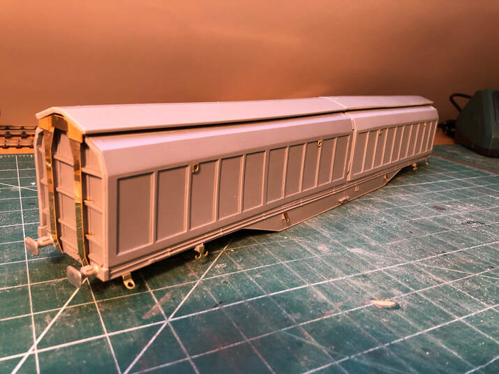
The Buzz Models IWA Kit is a great benchmark for a new beginner to the O gauge scene and kit building. With limited amounts of Brass work and a resin body It makes for a fairly easy construction process. This kit has a price of £95 + £5 P&P, however doesn't include any wheels. The recommended wheels to be fitted to the wagon are the Slaters 7122D, and can be supplied directly from Buzz for an additional £18. Giving it an overall complete kit price of £118. Obviously the paint is down to the buyer! We've only got ours to the primer stage at this current time.
The kit features a full set of easy to follow instructions which make it the perfect kit for some-one who hasn't done something of this nature before, and is considering taking the leap with a first kit but is concerned on price. We've included an in-depth review below.
You can purchase these kits by sending an email to; - [email protected] or going to there Facebook Page. Alternately you'll be able to purchase from the Buzz Models trade stand at various exhibitions up and down the country, including our exhibition in November 2019.
We'd like to take the time to Thank Andrew at Buzz Models to give us the opportunity to support his business and take a look at his kit. The IWA will also feature on our Roadshow stand visiting various exhibitions across the next 12 months. (Please see our Facebook page for the most up to date Information)
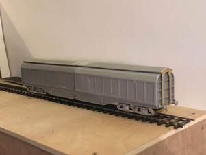
The Body
|
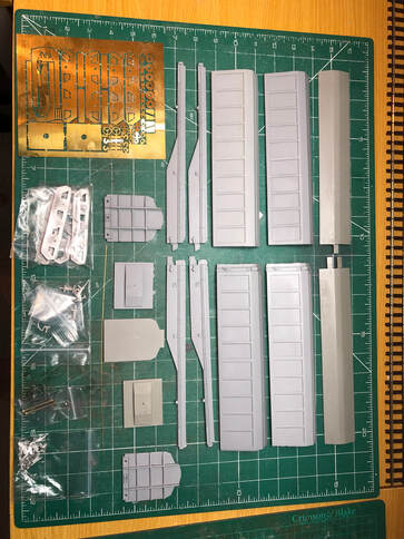
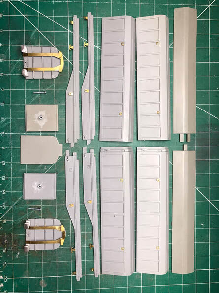
On opening the box the first thing I usually do is lay out all the parts and check everything is there. The resin parts look good and crisp and everything matched up to what the instructions said should be there. I realise the normal thing to do is throw the instructions away (I am male!) but always have a full read through a couple of times before making a start and keep them to hand during building to refer to, even if I do jump back and forth.
I made a start with cleaning up the resin parts and checking them against each other, there is some flash on the parts but with a couple of different files this is easily removed. At this point I also opened out the slot to take the draw hook of the coupling later on. All were pretty square and didn’t need straightening out (resin parts can become slightly twisted) and very few if any air bubbles were noted. The instructions suggest filling any air bubbles at this point, however if any are missed (I may have done) they can always be filled later on. Once cleaned up these were given a soapy wash to remove any agents from the moulding process. |
|
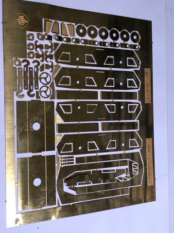
At this point I started to look at the etched parts and the instructions to work out what goes where. The picture in the instructions does have the part numbers listed, but being in black and white the numbers are difficult to make out. A quick email to Andrew and he forwarded on a digital copy of the instructions, the part numbers now clearly visible and my assumptions confirmed (I have suggested it may be worth adding the part numbers in white).
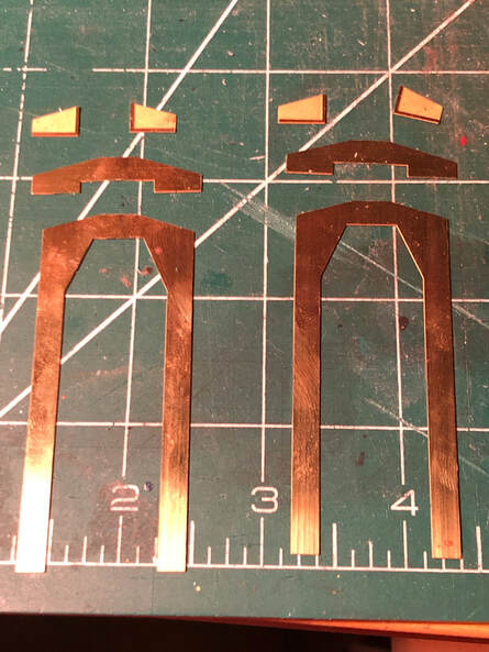
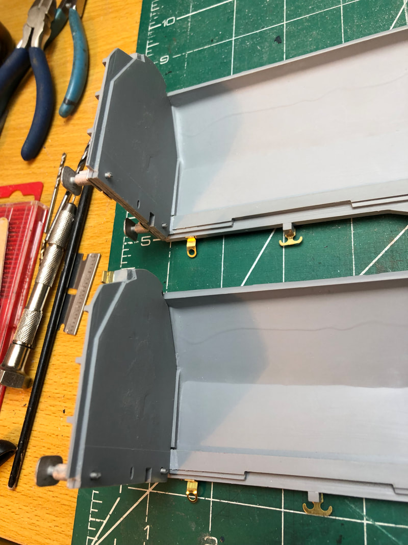
I added all the etched parts (hand brake wheel excluded) and buffers to the resin parts using Cyanoacrylate (super glue) as per the instructions, it’s so much easier fitting these parts on a flat workbench than making the body up first then trying to add them. - The buffers have a slight moulding line through the centre, again easily filed away. - The four anchor points for the four corners of the wagons have a half etched line on them, this needs bending 90 degrees with the half etch on the inside, then bending back around 45 degrees in the opposite direction just above the eye. - The four etched parts for the bodyside need bending 90 degrees with the etch on the inside and a small amount of the ribbing removing. Parts 1, 3 & 6 go together to make the end pieces. I put these together with Cyanoacrylate (super glue) but could be soldered. Then I used a small amount of impact adhesive to ‘tack’ them to the resin parts to allow some movement while fitting. Then securing with Cyanoacrylate applied with cocktail sticks. |
|
|
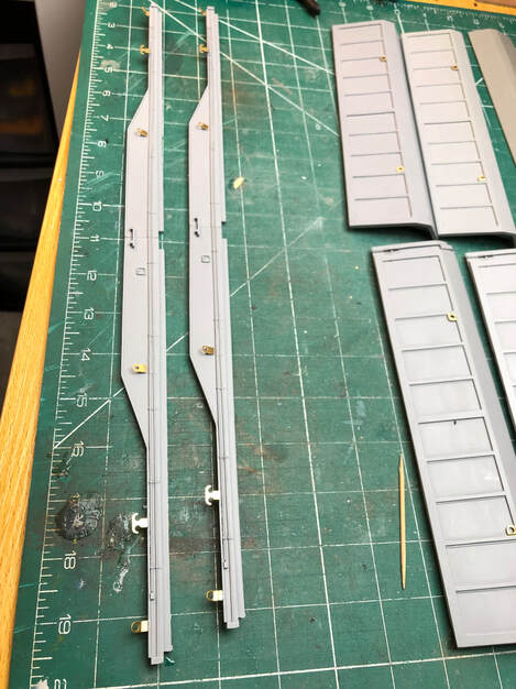
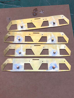
I also at this point drilled out the frame stretcher to take bolt to attach the bogies and glued the nut to the top side. Be careful and sparing with the glue on the nut so that you don’t get it on the threads!
|
Once all the etch parts are secure the resin parts can start to go together. At each point I offered up the parts and made sure everything fit how I wanted it before applying glue. I had missed a little bit of flash and this is your last chance to make sure the parts fit together well. Firstly fixing the two half’s of the underframe together.
Next adding the door with the central pillar, small modellers clamps are really useful here, Aldi often have multi packs for a sensible price.
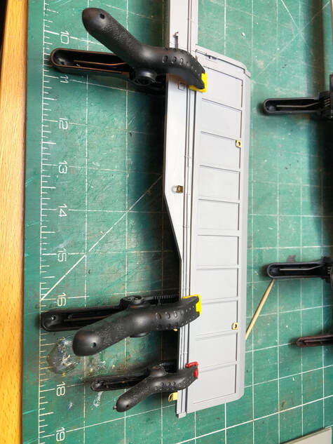
Finally adding the 2nd half of the doors and ends to make two ‘L’ shapes (make sure the ‘L’ match, I nearly ended up with a pair that didn’t!)
|
|
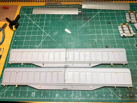
I left these to firmly set before putting the two ‘L’ shapes together.
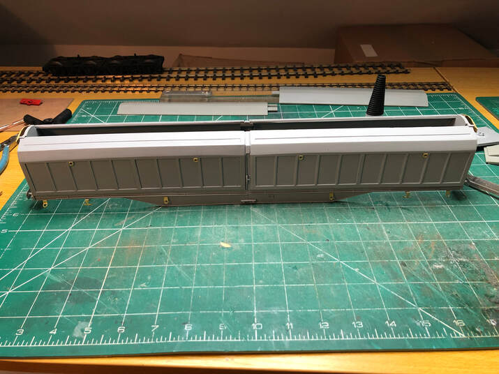
Insert the middle partition and frame stretchers, I used elastic bands just to hold everything together while the glue set.
The Bogeys
|
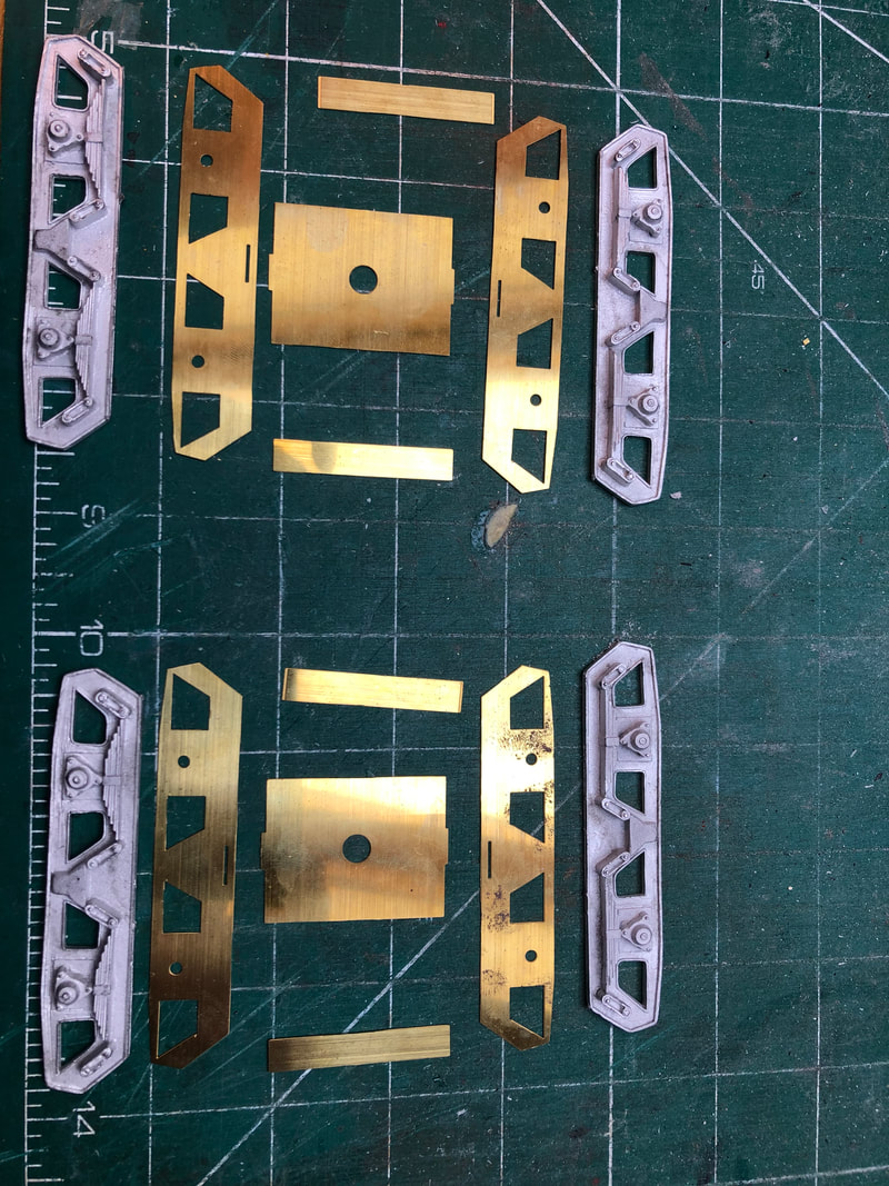
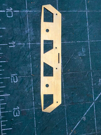
Once the body was complete I laid out the components of the bogies, all the etched parts cut off the fret and tidied up and had a dry run of putting them together. At this point I re-read the instructions and figure that it would probably be a good idea to mark out and drill holes in the side frame etches for the brake blocks before building the frames up. I marked out and drilled a 1mm hole where the brakes would be fitted to add later on.
|
|
|
I also trimmed the bogie channels and folded them up.
|
|
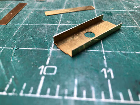
I also trimmed the bogie channels and folded them up.
Next I soldered the bearings into the side etches.
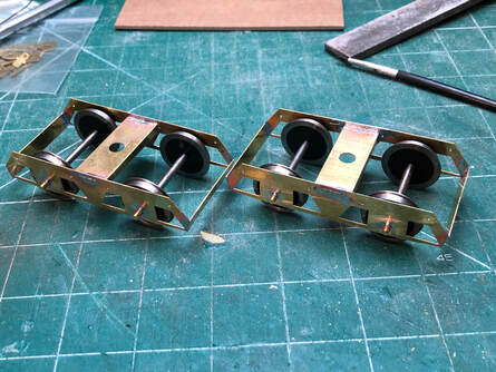
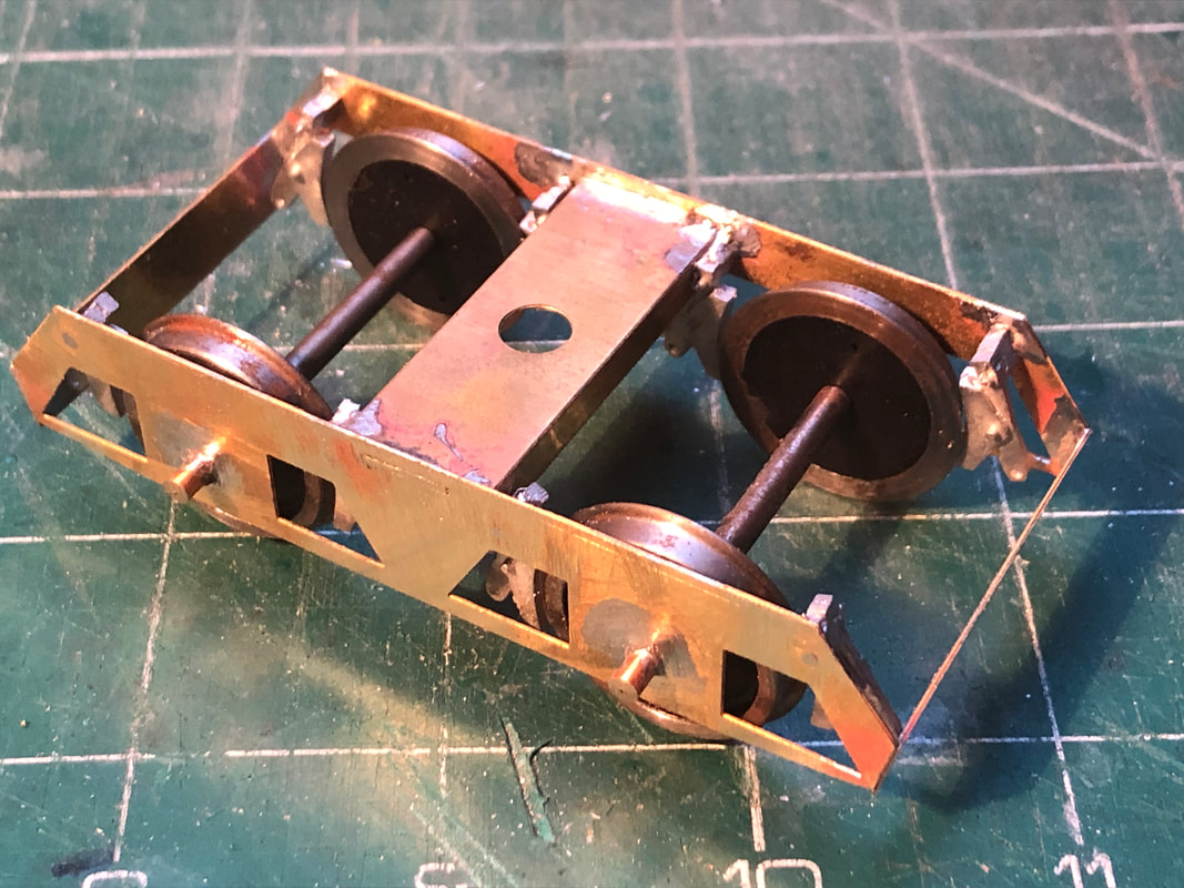
Once all the component parts were prepared I set about building the sub frames, soldering the bogie channel to one side frame before slotting the wheels in and soldering the other side on. This is where I went wrong! Guess who soldered the first side frame on the wrong way round! Once both side frames were fixed I then added the end stretchers to complete the sub frame.
Once all the component parts were prepared I set about building the sub frames, soldering the bogie channel to one side frame before slotting the wheels in and soldering the other side on. This is where I went wrong! Guess who soldered the first side frame on the wrong way round! Once both side frames were fixed I then added the end stretchers to complete the sub frame.
|
|
|
Next job was to fit the brake shoes, this being made much easier by drilling out holes while the side frames where flat. I initially super glued them in but I decided to have a go at soldering them after having some trouble with the glue. I should have reached for the soldering iron first as this was much easier.
|
|
|
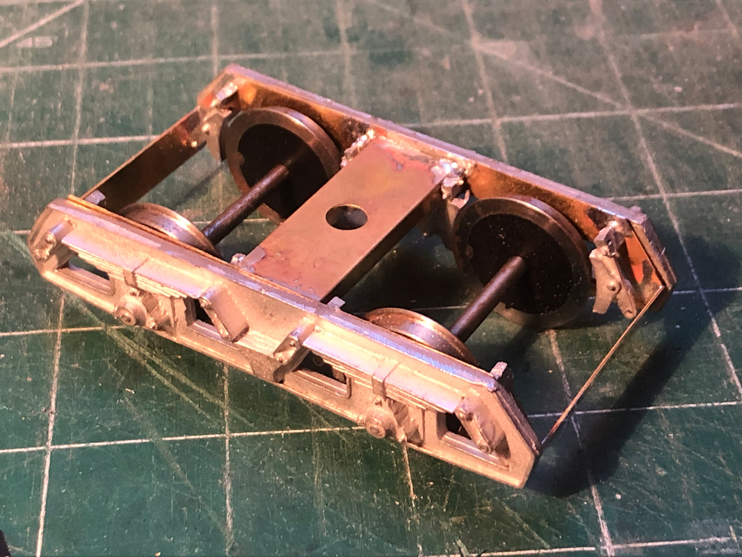
Last job was to fit the white metal bogie frames on the sub frame, this needs the axle boxes carefully opening out to take the bearing of the sub frame. This was done with trial and error taking a little at a time out of the axle boxes with a drill bit larger than the bearings. Once a snug fit against the sub frame was achieved these were then glued on with a generous amount of glue.
Bogies where then fixed to the body using the bolts provided. |