Fitting a LoksoundV5XL Decoder to a Heljan Class 33/0
by MIOG Member Cameron Burgess
We’re asked over and over how you go about fitting decoders to loco’s. Whether that be a Standard Decoder or Sound Decoder. There are guides out there on how to fit these decoders but we thought it best to create our own in-house version. I will point out now that I am no expert decoder fitter, just writing up my experience of fitting one. I know the frustrations of buying your first O gauge loco and being unsure where to go from getting it out the box.
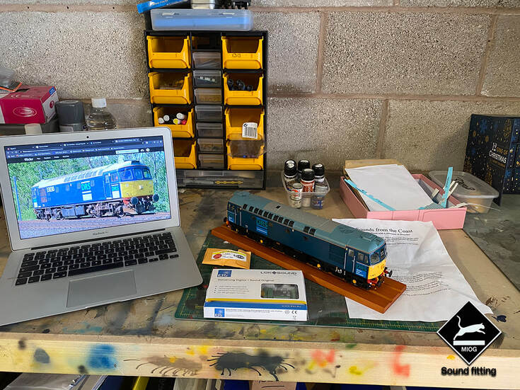
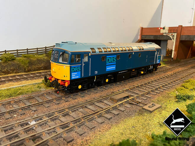
I’ve been saying I must do a guide on how to fit decoders for a while but the opportunity has never really presented itself. I recently purchased myself a DRS 33/0 from the new batch of Heljan Class 33/0’s and the time arose to finally write up how to fit a Sound Decoder. I’d like to thank Kevin at CostalDCC for supplying the decoder for this loco.
Fitting a decoder sounds like it should be straight forward, however if you’ve ever opened up a Heljan O gauge loco you’ll know this is not the case and can be somewhat overwhelming! It’s not like your standard Plug & Play 21pin decoders that your standard OO loco is fitted with. Heljan opted for the use of XL decoders in their locomotives. You can buy these from most good sound retailers, or even buy the decoders and have a go at the sounds yourself. There is a choice of solder pads or screw terminals available. I personally opt for the screw terminals, it reduces the amount of time you’ll need to spend soldering and messing around with flux! This guide whilst it is designed for fitting a Class 33 with a decoder could be implemented to help with other classes of Heljan Loco’s however use this at your own peril!
Fitting a decoder sounds like it should be straight forward, however if you’ve ever opened up a Heljan O gauge loco you’ll know this is not the case and can be somewhat overwhelming! It’s not like your standard Plug & Play 21pin decoders that your standard OO loco is fitted with. Heljan opted for the use of XL decoders in their locomotives. You can buy these from most good sound retailers, or even buy the decoders and have a go at the sounds yourself. There is a choice of solder pads or screw terminals available. I personally opt for the screw terminals, it reduces the amount of time you’ll need to spend soldering and messing around with flux! This guide whilst it is designed for fitting a Class 33 with a decoder could be implemented to help with other classes of Heljan Loco’s however use this at your own peril!
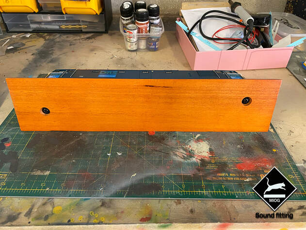
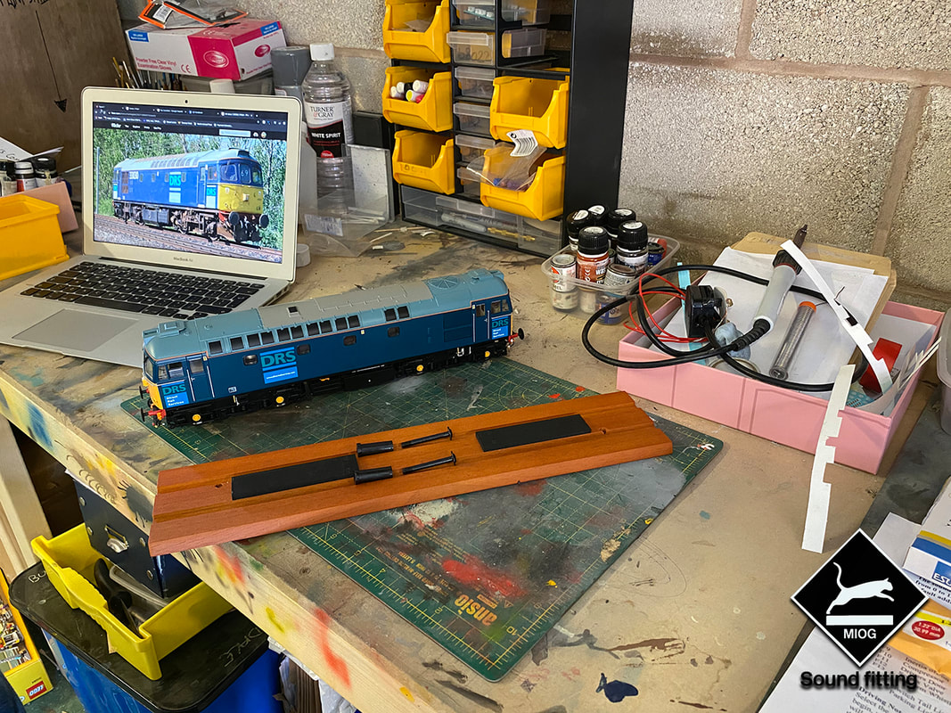
If you’ve just got your loco out the box you’ll need to remove the loco off the wooden plank. This is simply by removing the two screws underneath which will then release the loco off the plank and allow us to access the screws holding the body to the chassis.
When removing the screws for the body be careful to hold the loco to prevent any damage when the screws are removed. Upon removal of the screws you’ll be left with two screws, plastic stoppers, your loco and your wooden display plank. We no longer need the display plank so this can be placed away.
Now we have the loco off the plank. I’d recommend giving the loco a quick test run on DC (where possible) to ensure that your loco works. It’ll be a wasted effort to fit the decoder if the loco doesn’t work.
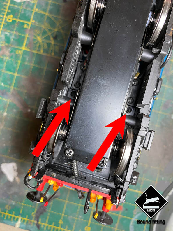
The main body for the loco is held on by 4 Screws which are located either side of the motors (2 Screws at each end). These can be accessed in between the motor block and the plastic bogie side frame. If you struggle to gain access the bogie frames simply clip off. A decent cross-head screwdriver will give you adequate space to undo these. You’ll need to remove all 4 screws in order to free the body up and allow it to lift off. The screws needing removal are marked in the picture below.
The main body for the loco is held on by 4 Screws which are located either side of the motors (2 Screws at each end). These can be accessed in between the motor block and the plastic bogie side frame. If you struggle to gain access the bogie frames simply clip off. A decent cross-head screwdriver will give you adequate space to undo these. You’ll need to remove all 4 screws in order to free the body up and allow it to lift off. The screws needing removal are marked in the picture below.
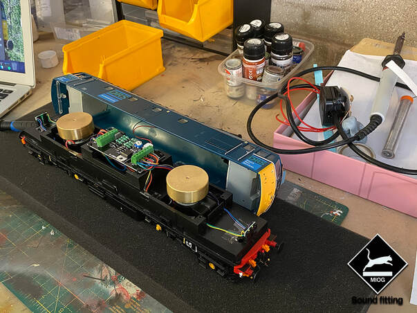
Once you’ve removed the 4 screws the body should simply just pull away from the chassis. I’d lay this flat back on its wheels and then gently raise the body off the chassis. Being gentle not to force it too much as the fan lead is attached to the main circuit board. You’ll need to remove this in a moment.
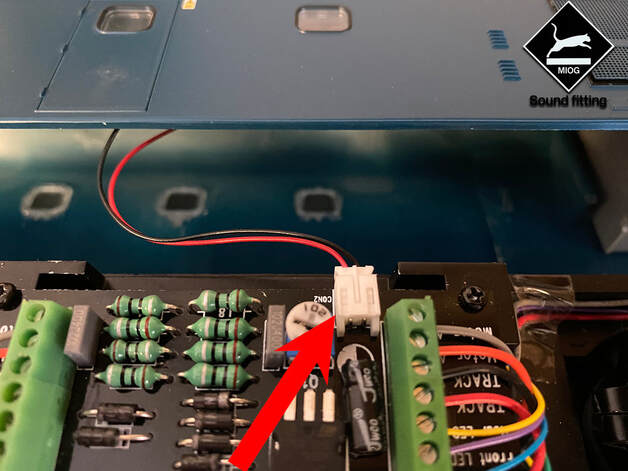
Upon removing the fan from the circuit board you’ll get a good look at the circuit board. Simply use a flat head screwdriver to push the white socket out. (Marked with the arrow on the photo below).
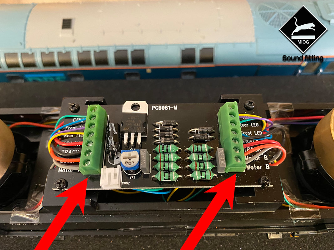
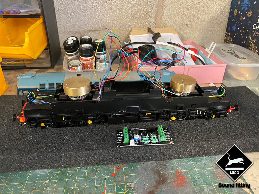
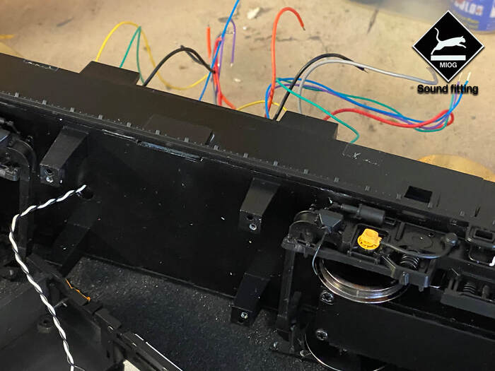
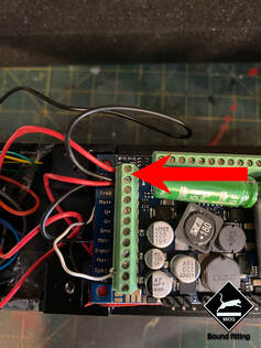
The way that the Heljan Locos are wired is almost like two independent locos. You have wires from the two motors one at each end, your track pickups and Head & Tail lights from each end. You'll need to unscrew the blocks (marked with the arrow) and simply pull the wires out of both sides of the circuit board. You'll need to remove these first before you can remove the PCB. Removing the wires from the PCB will allow you to remove it. To remove this there are 4 screws (in the corners) of the PCB simply unscrew and it should pull out.
A little tip before beginning the process of removing the wires, take a photo of the wires in the Heljan PCB before removing them.
A little tip before beginning the process of removing the wires, take a photo of the wires in the Heljan PCB before removing them.
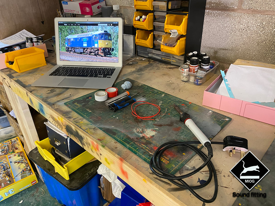
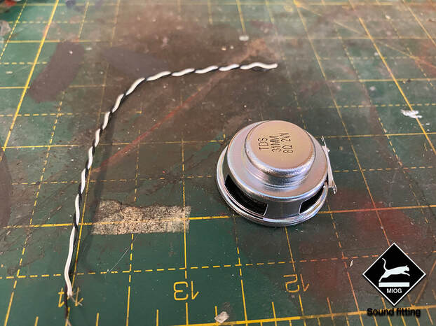
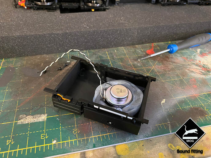
Now we’ve removed the PCB from the loco, the next job will be to solder the wires onto the speaker that will be fitted into the Fuel Tank. I’m aware that some speakers come pre-soldered. The speaker we ordered came with wires and soldering required before fitting. With the 33 this is the only bit of soldering required. Purely because Heljan had the hindsight to actually fit the loco with longer wires, (Normally they just about reach the PCB and normally need extending for fitment of a decoder) You’ll need two pieces of wire that will be long enough to get from the fuel tank to the decoder which will sit in a similar position to the original PCB which we've now removed.
Solder the wires to the two tabs on the speaker using a small amount of solder and ensure that each wire doesn’t touch the other side, if you're using a bigger wire than I did. Once you’ve soldered the wires to the speaker then we’re ready to fit it into the fuel tank.
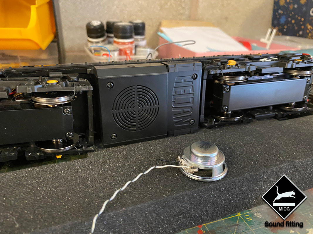
Now we need to remove the fuel tank off the chassis to allow us to fit the speaker. This is done by removing the 4 screws that are on the underside of the model. Simply unscrew and the tank should just fall away.
Once you’ve removed the tank its time to fix the speaker into the tank. For this I just use blue/black tack to create a seal around the speaker. It gives the speaker something to be fixed to rather than it rattling around in the fuel tank when its travelling around the layout.
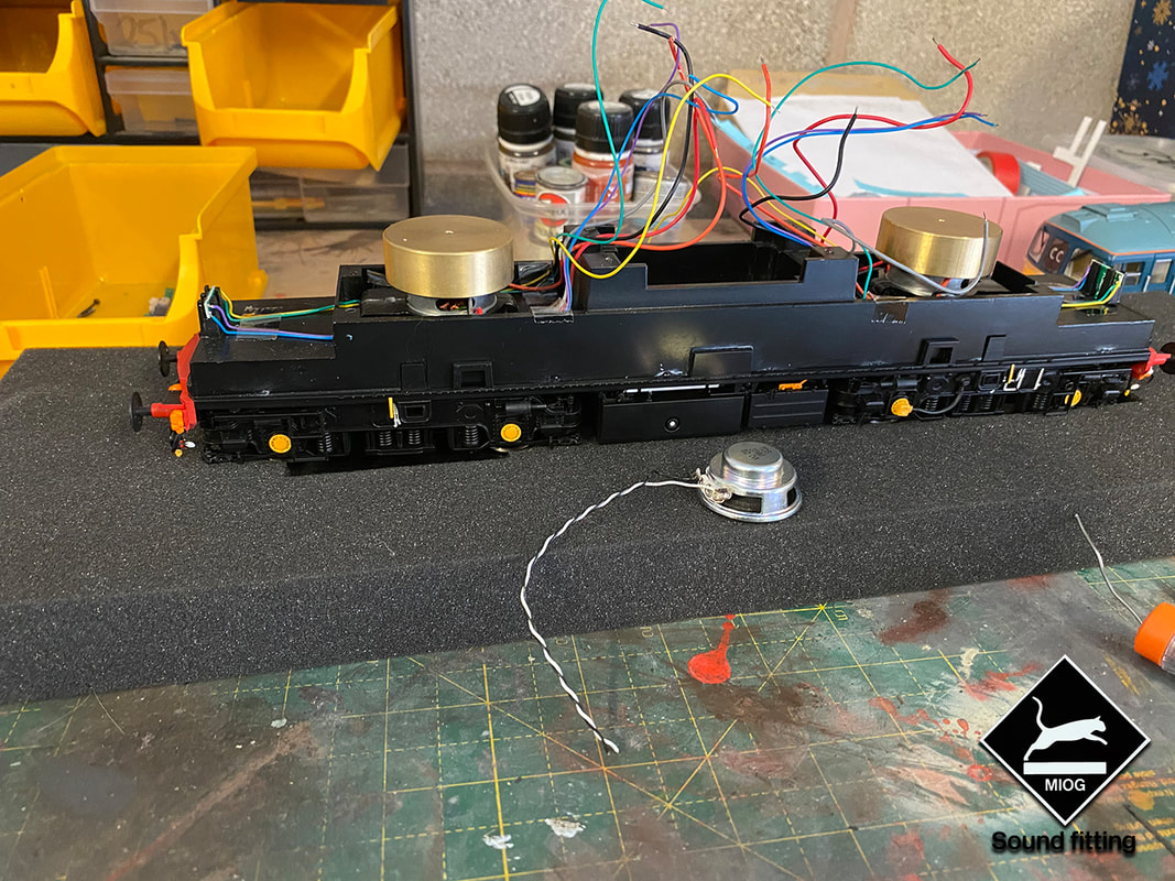
Now we have secured the speaker to the fuel tank we need to thread the speaker through the hole already predrilled into the chassis, so that we can connect it to the decoder shortly. Once we’ve done this we can re-attach the fuel tank to the chassis using the 4 screws that we removed not long ago.
Now we have secured the speaker to the fuel tank we need to thread the speaker through the hole already predrilled into the chassis, so that we can connect it to the decoder shortly. Once we’ve done this we can re-attach the fuel tank to the chassis using the 4 screws that we removed not long ago.
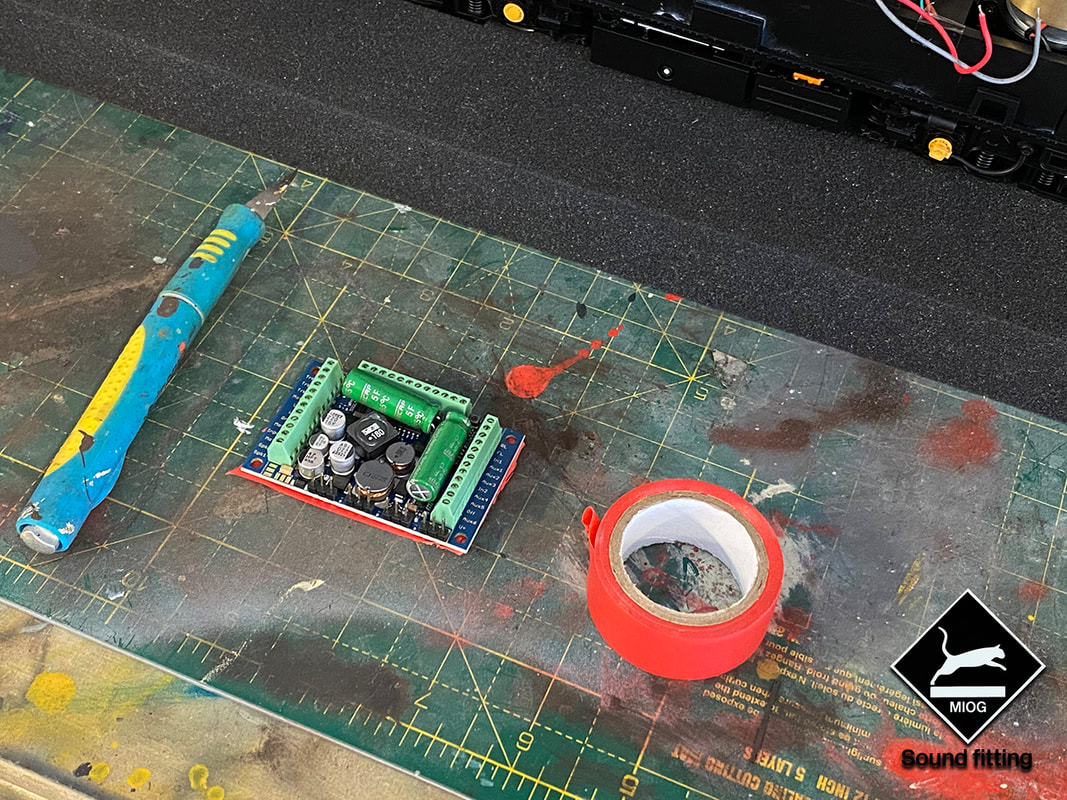
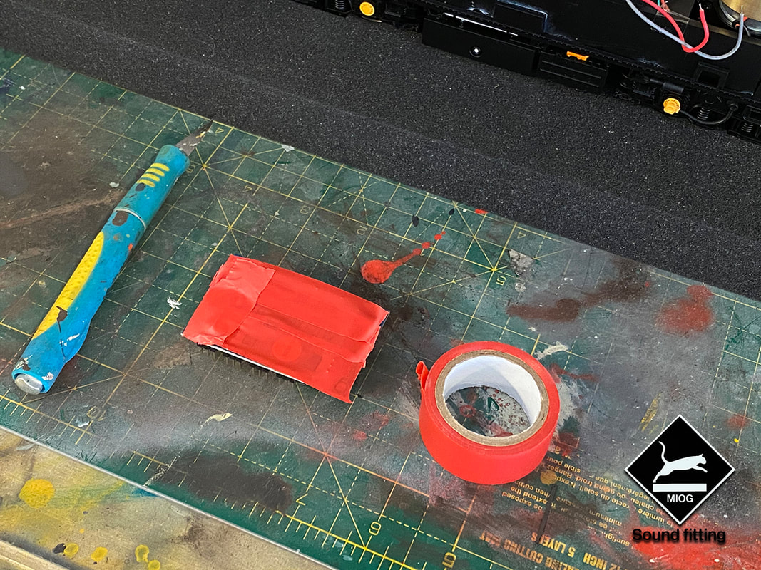
Before we start to wire the decoder up we need to insulate the bottom side of the decoder before we place it into the chassis. Because the chassis is metal we need to insulate the bottom side of the decoder to ensure that it doesn’t short out when we add power from the track. I use some insulating electric tape to the underside of the decoder. Once I've done that I use a scalpel to just trim up the edges to keep it nice and tidy.
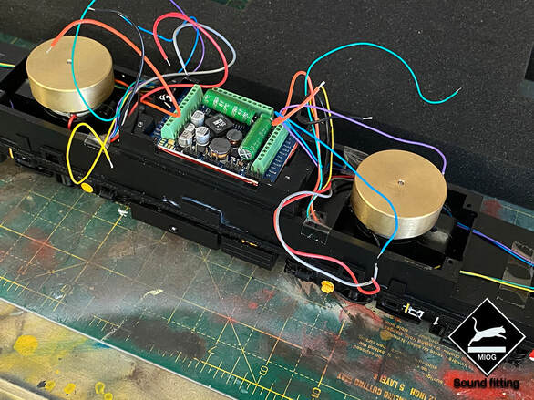
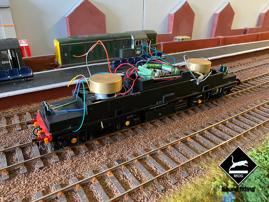
After insulating the decoder we are now ready to place it into the locomotive. At this time we won't be fixing it into place due to some cable management required later on in the process. The decoder simply drops into a ledge just under the place where the original loco PCB was located. Which gives you a good solid working base to start wiring all of the wires into it.
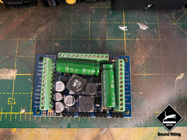
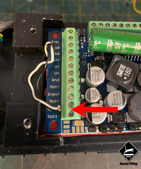
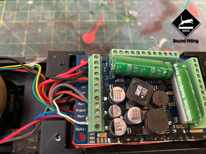
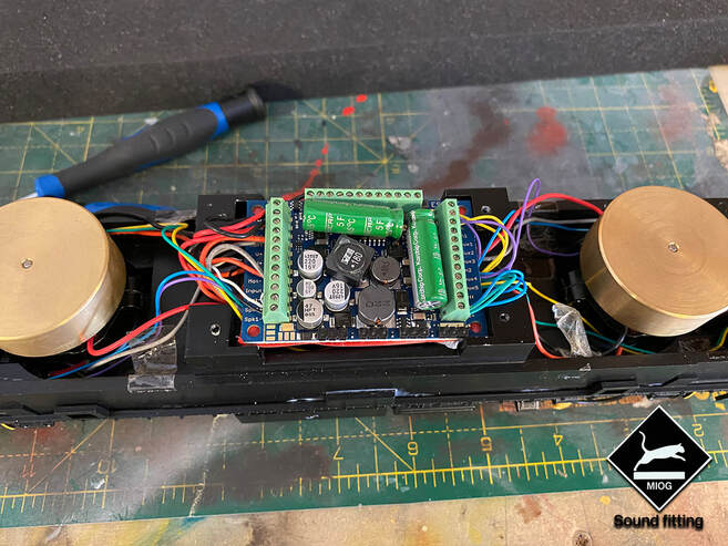
Firstly let's start by wiring the speaker into the decoder that we’ve recently attached into the fuel tank. This is the simplest thing to do, as it's just two wires and they have there own slots on the decoder. It doesn’t particularly matter (or i’ve found) which way round you wire the speaker into the decoder. So on the left hand side of the decoder we’ve got Spk1+ & Spk1- these are the two ports that we are going to be wiring the speaker into. You’ll need to ensure you have taken the plastic coating off the end of the wire to ensure we make contact. We can now insert the bare wire into the correct terminals and screw down ensuring the wires are secure. These are shown on the image below with an arrow.
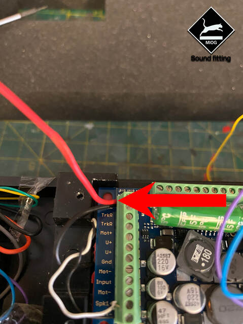
Next to be put into the decoder will be the track power. These are the feeds that come from the bogie to allow the loco to get power from the track. You have a set of feeds at each end of the locomotive (1 Per bogie) that need attaching. What can become confusing as we continue is that they’re opposite at each ends. So in order to connect them and not make the loco short you need to mix opposite colours
These need to be added into the TrkL block on the left hand side of the chip, and then repeat the process with the opposite side and place them into the TrkR. At this point there should be 4 wires in the decoder in the Trk Outputs. 2 from each end of the Loco. In the case of the 33 this is 1 black & 1 red into each of the L&R Terminals from each end of the loco. At this point I find it best to try the loco on the layout (It won’t move but you’ll at least be able to test the chip). This will allow you to check that you’ve wired the Trk Feeds up properly without creating a short in the loco. If so you’ll also be able to try the sound functions and get an idea of what your loco sounds like. If everything is successful then we continue and add the motors.
Again as with the track feeds we need to repeat the process with the Motors. These are also reversed at each end so you’ll need the opposite wires from each motor. These again go down the left hand side of the decoder in the Mot+ and Mot- terminal. 2 wires in each. 4 Wires in total across the two terminals. In the case of the Class 33 its 1 Orange & 1 Grey, from each end into the 2 terminals giving you a total of 4 wires in the two different Terminals.
Again you may wish to test this on the layout to ensure that you've wired the motors in the correct way. Purely because if you finish and put your lid back on you might find your loco ends up trying to pull itself apart when the motors are trying to go in opposite directions!
Again you may wish to test this on the layout to ensure that you've wired the motors in the correct way. Purely because if you finish and put your lid back on you might find your loco ends up trying to pull itself apart when the motors are trying to go in opposite directions!
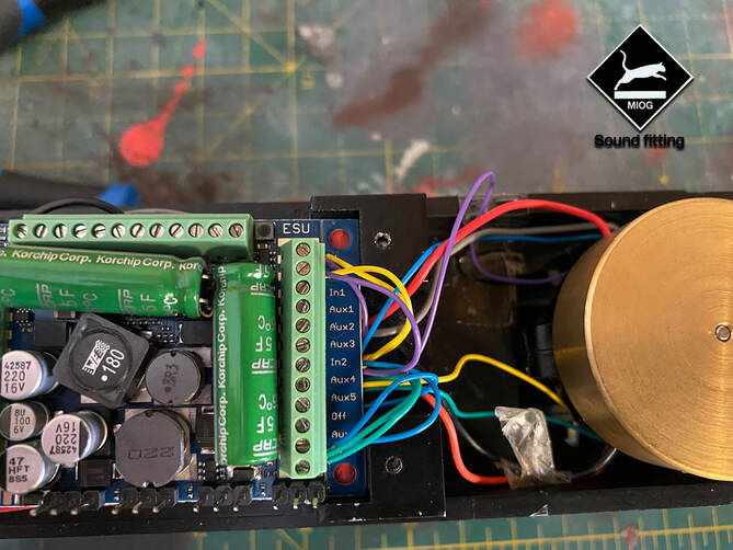
Now all that is left to do is fit the heads and tail lights. These are the 4 thinner wires that are fed from the LED’s located in the lighting circuits under each cab. This should be 8 wires in total left to fit to the decoder. Again much like the Motors and Pickups you have to wire these in Reverse so when the Loco is facing in 1 direction you can wire it to show Headlights on 1 end and Tail Lights on the other. But as different to the other circuits we also have a Common, this allows the lights to show all the time when the light function is activated. In the case of the class 33 it doesn’t actually display any reds. Just White running lights. But it works in the same way for all other Heljan Locos.
These wires all go into the right hand side of the chip, the opposite side to where we were working to get the track & motor functions. So for this in the case of the Class 33, The common wires are the Green & Blue, all 4 of these need to go into the U+ terminal.
These wires all go into the right hand side of the chip, the opposite side to where we were working to get the track & motor functions. So for this in the case of the Class 33, The common wires are the Green & Blue, all 4 of these need to go into the U+ terminal.
Once you’ve done that you’ll need a 1 purple from one end and a 1 yellow from the other to go into the FL terminal. You repeat the same process for the RL Terminal. Once these are all screwed in the only thing that is left to do is test that they are wired up correctly for the direction of travel. If this isn't the case, then simply swap the terminals over.
A little cable management in the loco to tuck all excess wires under the chip and the wiring is complete. On most Heljan locos you have the choice of wiring up the Loco Fan. This can be done by cutting the Plastic connector off the end of the wires. Do this as close to the connector as possible. Wiring into the Aux2, (Chip Dependant) and one in the Common and it will be on a Function key on your controller. I’ve not shown how to do this as I personally don’t enjoy using them as they’re often noisier than the actual loco sounds.
Once your happy with the tidyness of the wiring within the loco you can then fasten the chip down. Either using Blue/Black-tack or a double-sided sticky back tape to secure the decoder in place. This will also keep your wires nice and tidy within the loco once the body been popped back on.
Once we've finished this I'd recommend testing the loco on the layout to ensure that everything is performing properly before re-attaching the body.
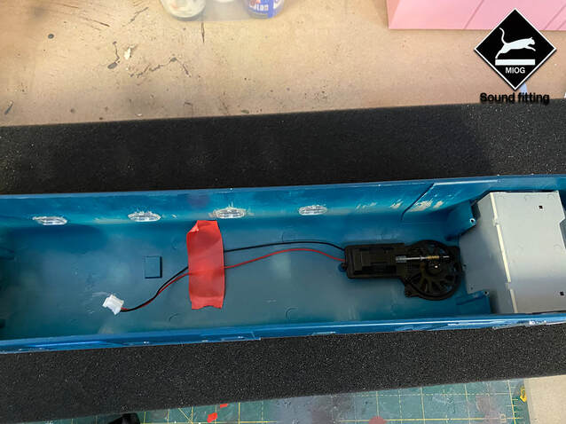
If you're not using the Fan like myself I always find it useful to tack the wires to the roof, so they don’t drop into the body and get tangled.
All that’s left to do is re-attach the body to the chassis using the screws we removed earlier. Once you’ve done this take your loco to your layout and it should be on Loco Address 3. You can then reprogram and play to your hearts content. We hope this guide has been of use to you and will help you build the confidence to take on future sound fitting projects!
Decoder & Speaker from : https://www.coastaldcc.co.uk/
Loco from : Any Heljan Stockist
Loco from : Any Heljan Stockist
Proudly powered by Weebly
