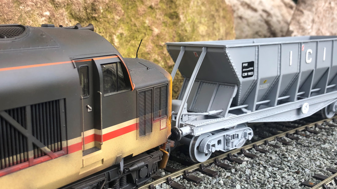
20151 leads an UID class 20 (possibly 20166) with a rake of empty ICI Hoppers at Chinley North Junction. T Baxendale courtesy of K Parker.
Out of the Box
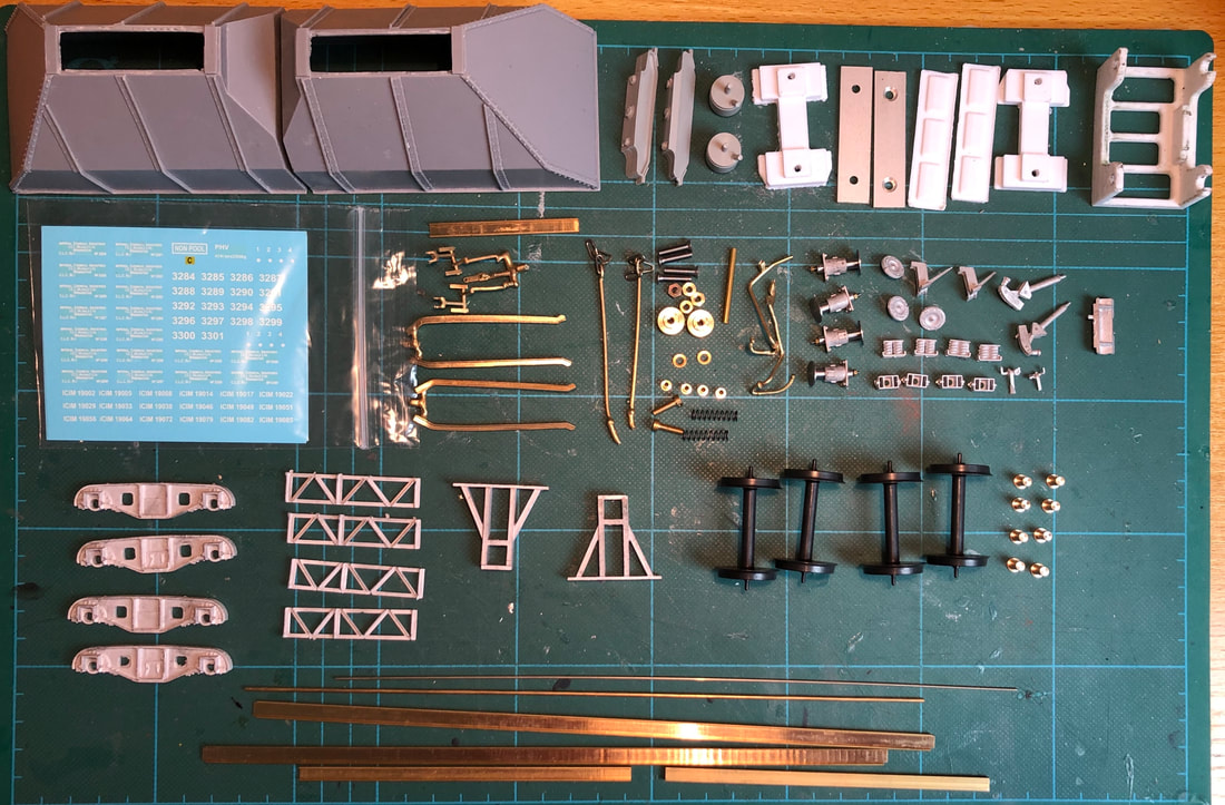
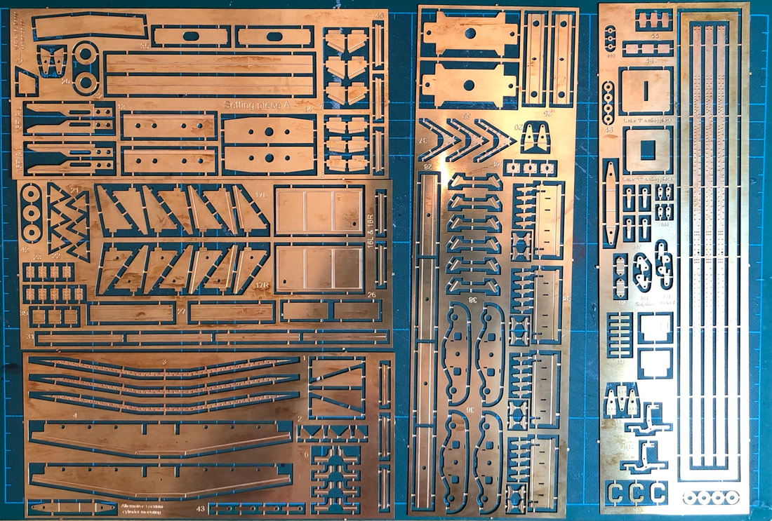
Out of the box the Signature Kits ICI Hopper certainly appears to be a comprehensive kit of parts for what is arguably an iconic wagon. There is an array of castings in Resin, White Metal & Lost Brass along with five sheets of etches and numerous sundry items. This kit is complete all bar paint and solder/glue with wheels, couplings and transfers all included. First job as always is a run through of the instructions. These appear to also be very comprehensive with both written and clear pictorial instructions.
|
|
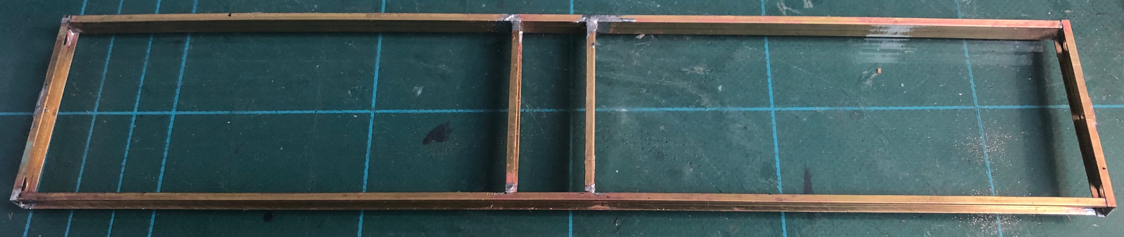
Chassis
This was never going to be a quick build, but with a couple of hours to spare I made a start picking out and preparing the first parts to build up the chassis. A hold and fold tool really is essential for building up a kit such as this, keeping the parts square without would be nigh on impossible. Also useful is a piece of sheet glass, it helps keep things square when soldering. I have a classic vehicle with flat wind screens so when they were replaced during overhaul, I kept the badly chipped ones we took out as spares just in case I needed them in the future, and they are also ideal for this purpose.
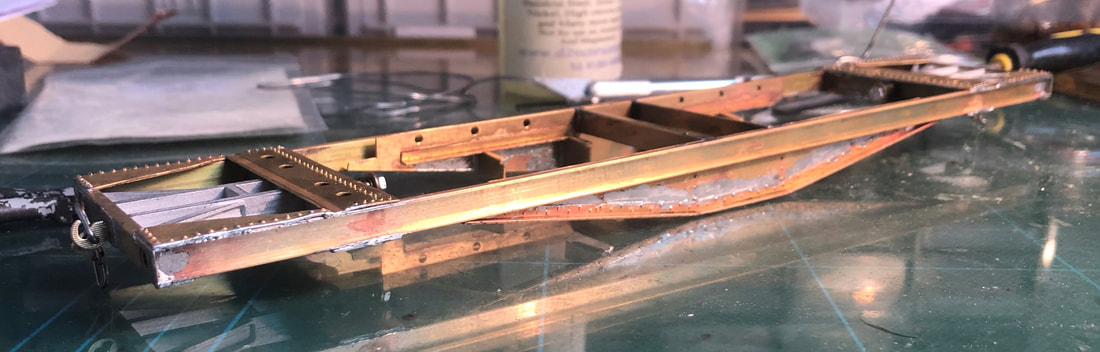
Firstly, folding up the buffer beams into a ‘U’ shape and soldering the coupling hook overlay in place, then soldering each solebar to the buffer beam’s creating two ‘L’ shape pieces before bringing them together. Next job is to fit the central crossbeams flush to the top of the solebar. I had a little trouble with this, but looking back I should have either taped or clamped the setting pieces in place before soldering the cross beams.
|
The front frame casting (White Metal) can now be cleaned up and fitted behind the buffer beam, I tacked this in with superglue just to help with the next stage. The instructions mention a requirement to drill a 2mm hole through this casting for the draw bar shaft, I fitted the casting and the bogie support mounts before drilling through so that I kept everything square. The bogie support mounts are fitted flush to the top edge of the solebar 5.25mm apart. Again, the instructions give some additional advice here where by you can leave the central most bogie supports off as they are not visible once completed, I decided to keep them.
|
|
Once the rivets are pushed through the corner gussets, the upper bogie support can be soldered into place making sure you have the chassis and parts the right way up and the groove in the bogie support outermost on the wagon. My tool kit is quite sparce in some respects so I use a small bradawl for pushing rivets through (I am sure some will be horrified at this, but it works for me). I then cleaned up and slotted through the draw bar securing with the nut provided and a tac of solder to prevent it from coming loose.
Turning the chassis over the lower corner gussets can be added along with the lower bogie support and the boss for mounting the bogies. At this point I started to realise that the soldering iron I had been using really wasn’t up to the job. But alas I persevered!
Turning the chassis over the lower corner gussets can be added along with the lower bogie support and the boss for mounting the bogies. At this point I started to realise that the soldering iron I had been using really wasn’t up to the job. But alas I persevered!
|
|
|
|
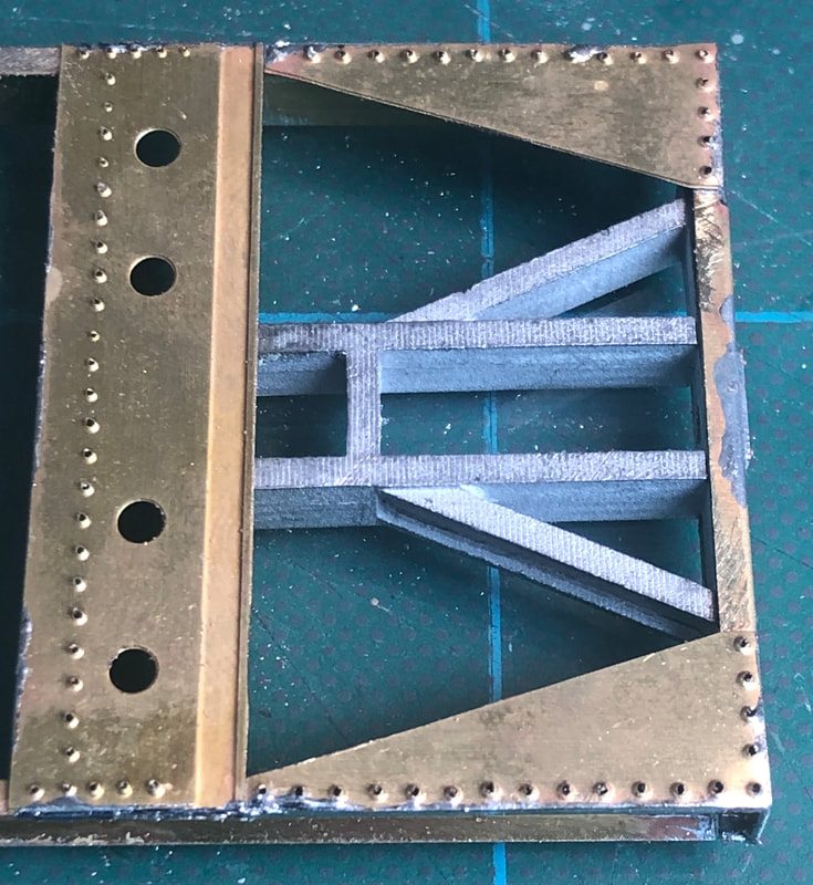
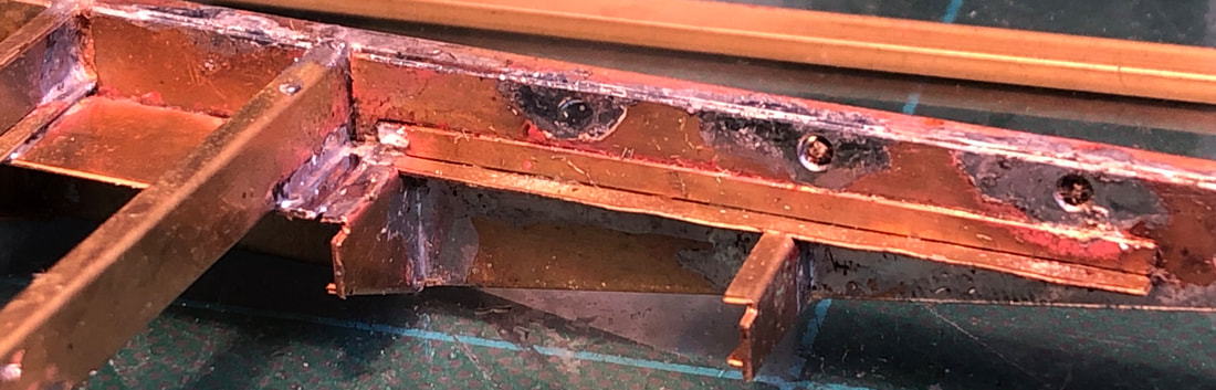
Turn the valances over and laminate the riveted overlay into the right-angled section created earlier. These sub-assemblies can then be soldered onto the chassis. Note that the valance with the hole drilled through sits opposite the solebar with a hole in it.
|
|
|
There is another overly which runs the length of the solebar, once riveted this again is laminated into place ensuring that the hole in the overlay goes on the same side there is a hole in the solebar.
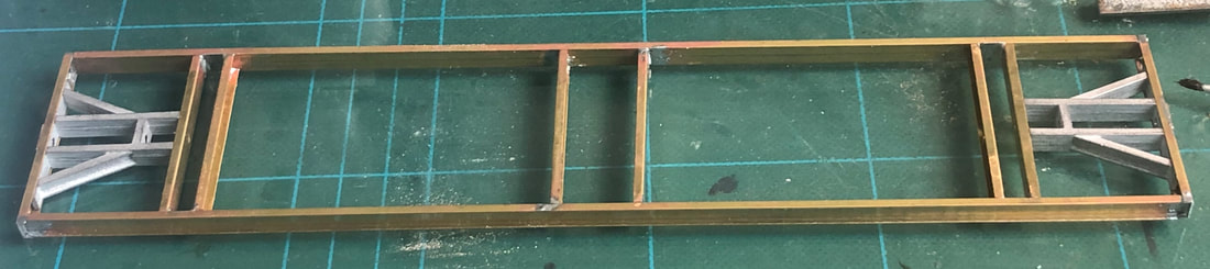
The next stage I unfortunately failed to photograph, the inner solebar extension pieces need bending using the end setting piece and soldering to the 5mm x 2mm ‘U’ channel before the whole assembly is fitted to the brackets earlier attached to the valance.
The next stage I unfortunately failed to photograph, the inner solebar extension pieces need bending using the end setting piece and soldering to the 5mm x 2mm ‘U’ channel before the whole assembly is fitted to the brackets earlier attached to the valance.
|
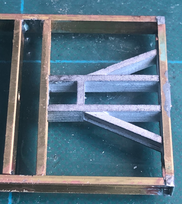
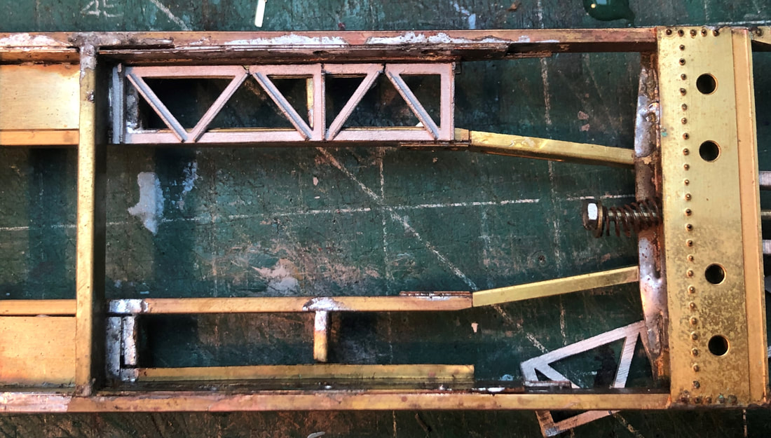
The white metal lattice pieces can now be fitted, securing with a small amount of super glue. These are handed so make sure you fit the right parts in the correct place. Next up will be putting together all the part for the door mechanisms.
|
|
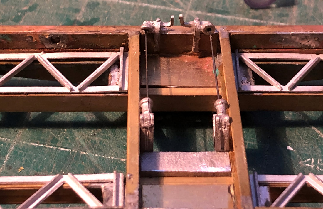
There is a White Metal mount which should sit snuggly into the centre of the chassis with a 1mm hole drilled through the face. This is achieved by using another part to locate it accurately. Once the mount is fitted then the door operating brackets can be fitted, these need a 0.8mm hole drilling in the boss face. This is to take a piece of 0.7mm wire which runs across the wagon and into the boss on the door opening lever’s which sit on the opposite solebar.
The handbrake shaft bracket can now be fitted to the vertical face of the door linkage support beam along with the brake gear compensating lever.
The handbrake shaft bracket can now be fitted to the vertical face of the door linkage support beam along with the brake gear compensating lever.
|
|
|
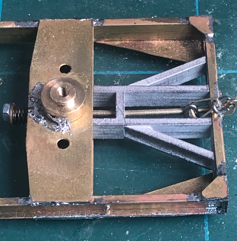
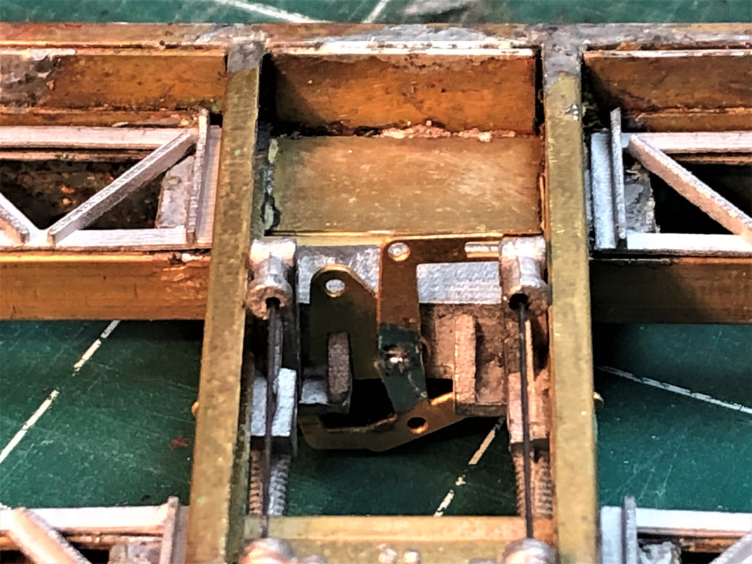
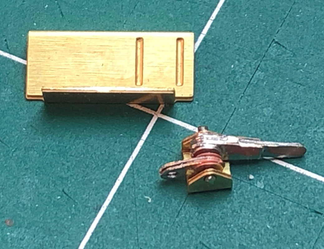
The next few stages are quite fiddly and this is where I struggled a little. The auxiliary mounting bracket is folded into a ‘Z’ shape and the hand brake trunnion into a ‘U’. At this point the instructions say to solder the trunnion to the mount, I unfortunately thought better and figured It would be easier to make up brake levers and fitting them to the trunnion first. In hindsight I should have probably followed the instructions! Two long brake levers and two short levers are soldered together back-to-back and spaced apart with the provided washers and slotted on to a length of 1mm wire. Make sure you keep the levers loose as it will help with fitting later on. This assembly is then slotted into the trunnion.
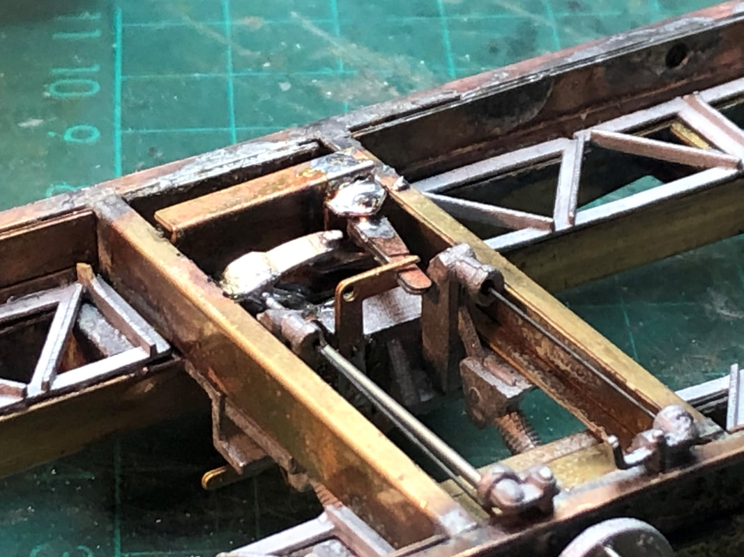
The whole assembly is then fitted to the wagon with the longer of the two brake levers slotted into the brake gear compensating lever with the shorter lever attached to the hand brake casting with a 1mm wire pin. 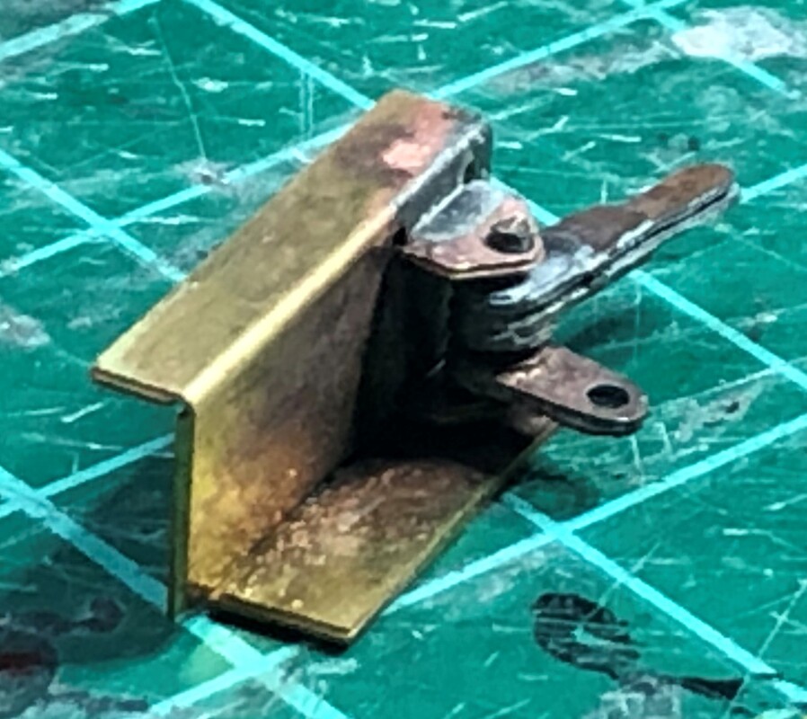
|
|
|
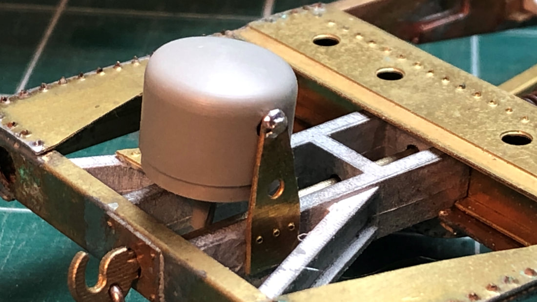
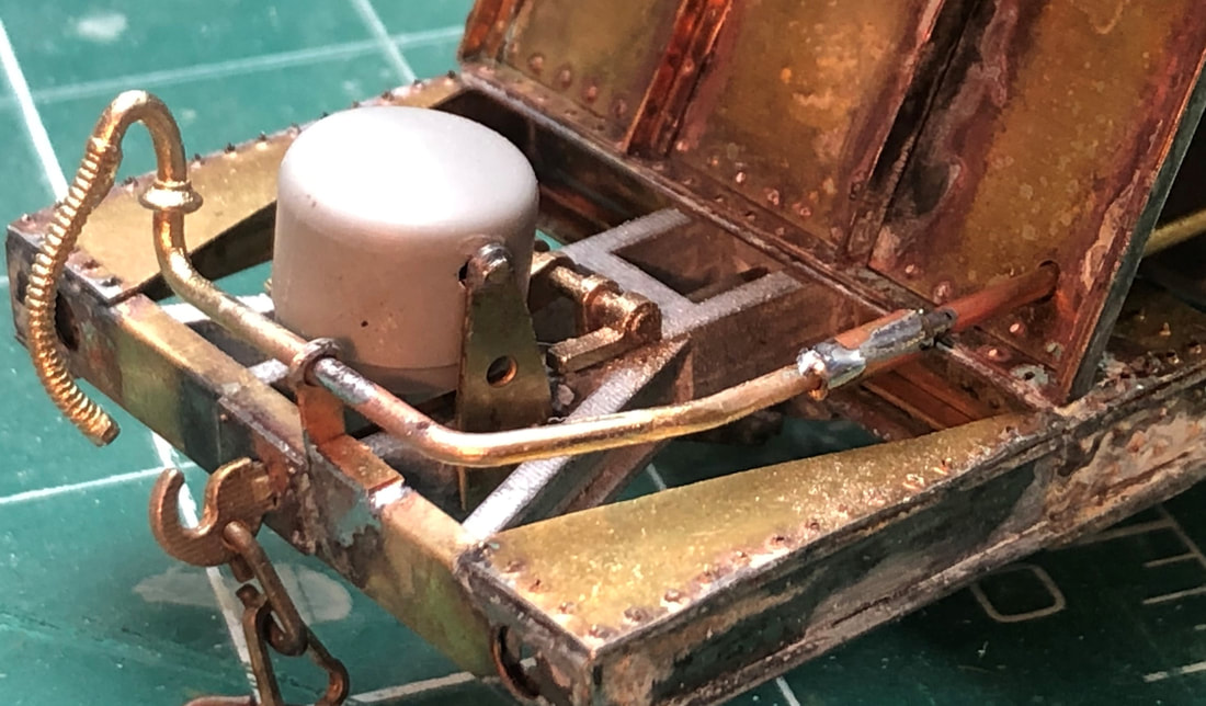
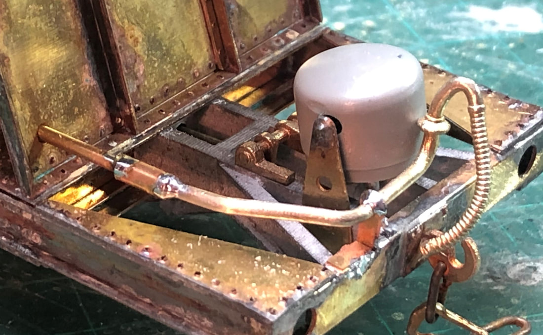
The resin vacuum cylinders require a 2mm hole drilling through the centre of them to take a piece of 1mm wire which is attached to the vacuum cylinder support brackets. These are both rivetted and one bent to a right angle. They are then fitted to opposite ends of the chassis, note the are handed and should be fitted with the angled bracket to the opposite side of the chassis to where the vacuum pipe will eventually go.
The brake linkage casting now needs slotting in, the ‘U’ shaped part of the casting should go around the spindle on the vacuum cylinder and the inner leaver should pass below the two short cross pieces of the framing. |
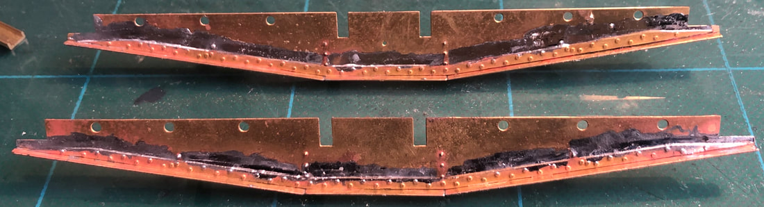
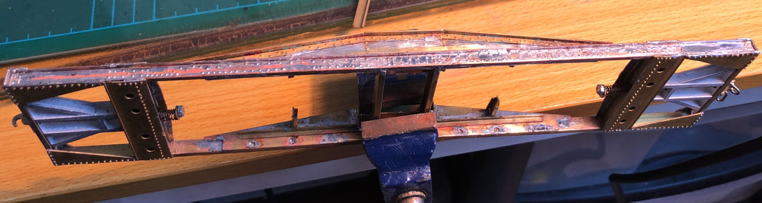
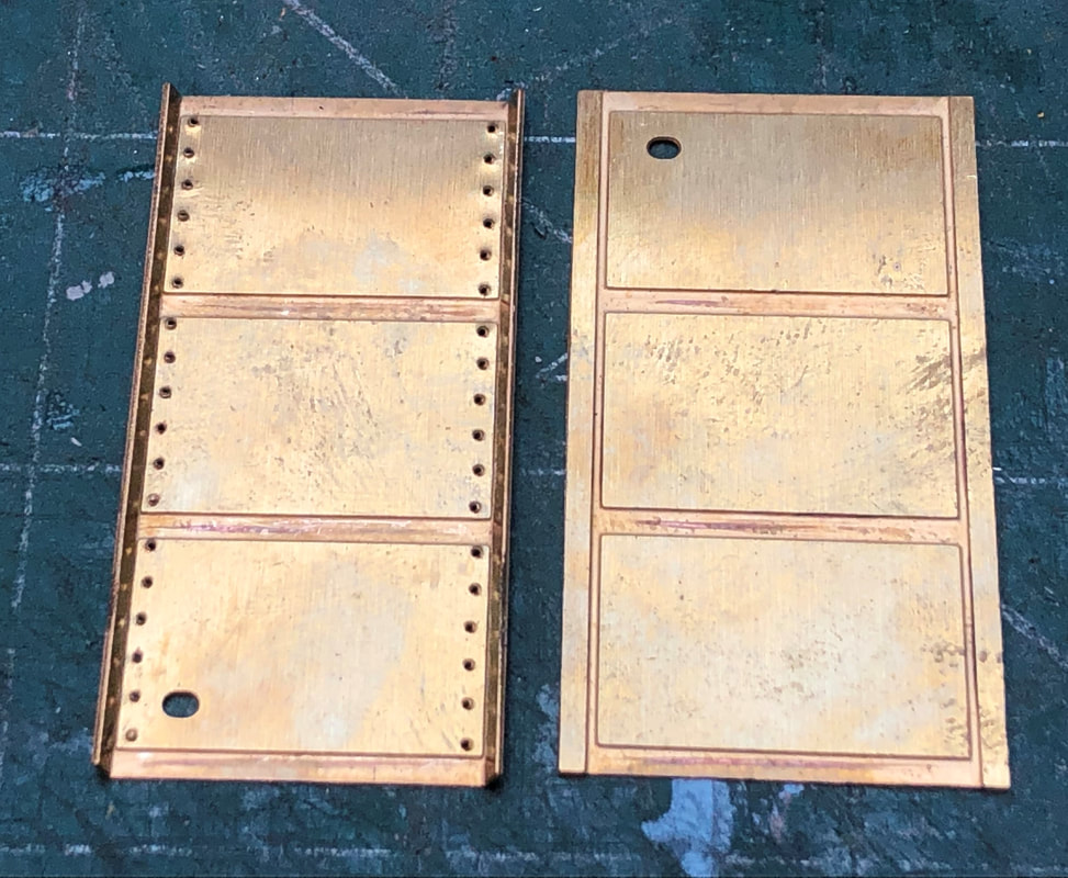
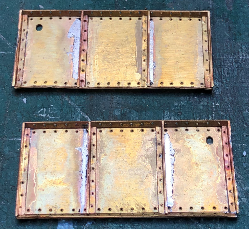
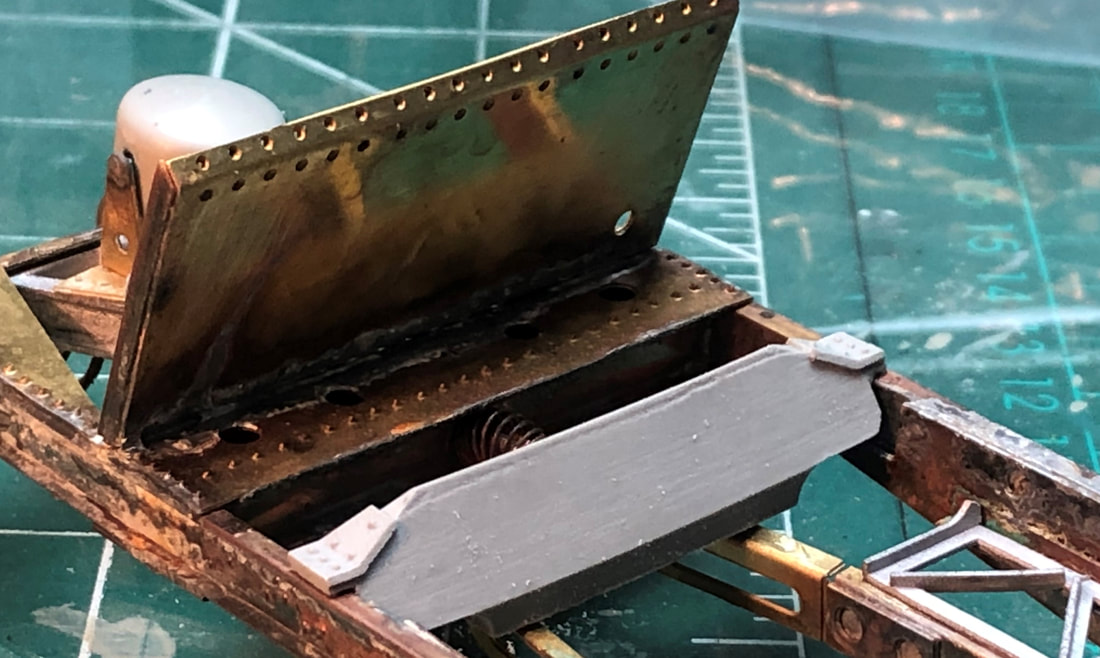
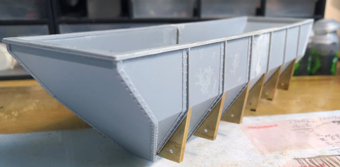
The outer tank end supports and the end stiffeners need riveting and the long edges bending to 90 degrees. The end stiffeners are then soldered into the half-etched rebates in the end supports ensuring all rivets are facing inbound.
These are then fitted to the solebar using the provided setting gauge. It may well be easier to leave thee off until the body is complete to aide getting them accurately spaced. The two cast tank support beams can also be fitted at this stage.
These are then fitted to the solebar using the provided setting gauge. It may well be easier to leave thee off until the body is complete to aide getting them accurately spaced. The two cast tank support beams can also be fitted at this stage.
|
|
|
|
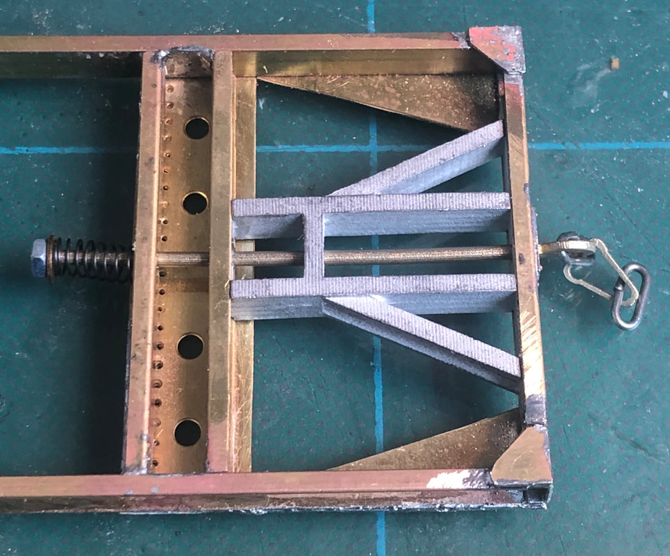
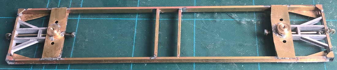
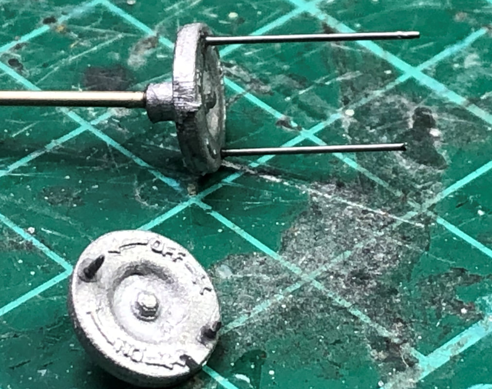
The hand brake wheels need 0.7mm holes drilling through the two dimples on the white metal castings to form the handles. I glued lengths of 0.7mm wire into the holes that were longer than required then trimmed back to around 2mm long. These are then fitted to lengths of 1mm wire approximately 38mm & 12mm long which then slot through both sides of the solebar respectively.
|
|
Body
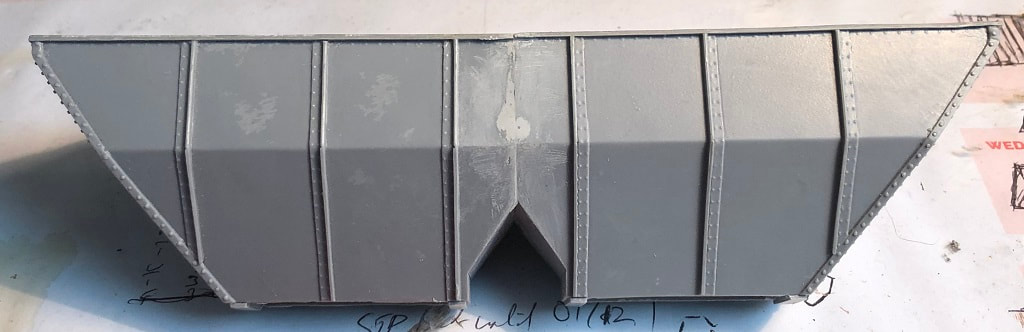
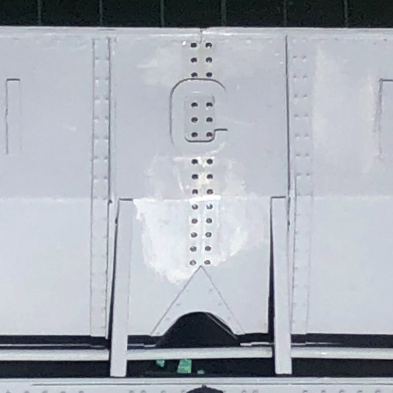
The main hopper body of the kit comes in two parts. These need to be fitted together squarely, the instructions recommend a two-part epoxy but I didn’t have any to hand so used superglue. I wouldn’t recommend this method as I didn’t get it 100% how I wanted, always use the right tools for the job! Queue taking it apart and starting again. The second time I (again!) used superglue but this time made sure it was absolutely square and clamped with small clamps and bulldog clips. Because I messed up the first time, I had a bigger gap than I should have between the two halves of the hopper, this is no detriment to the kit and if I had got it right initially I probably wouldn’t have had this issue. The problem with filling this gap down the centre of the body is that you risk damaging the rivet detail. Maybe a little blaze of me but I decided that I would just fill and file and worry about the rivets later, I have been looking at Archer Rivets for some time so maybe this is time to look into them again!
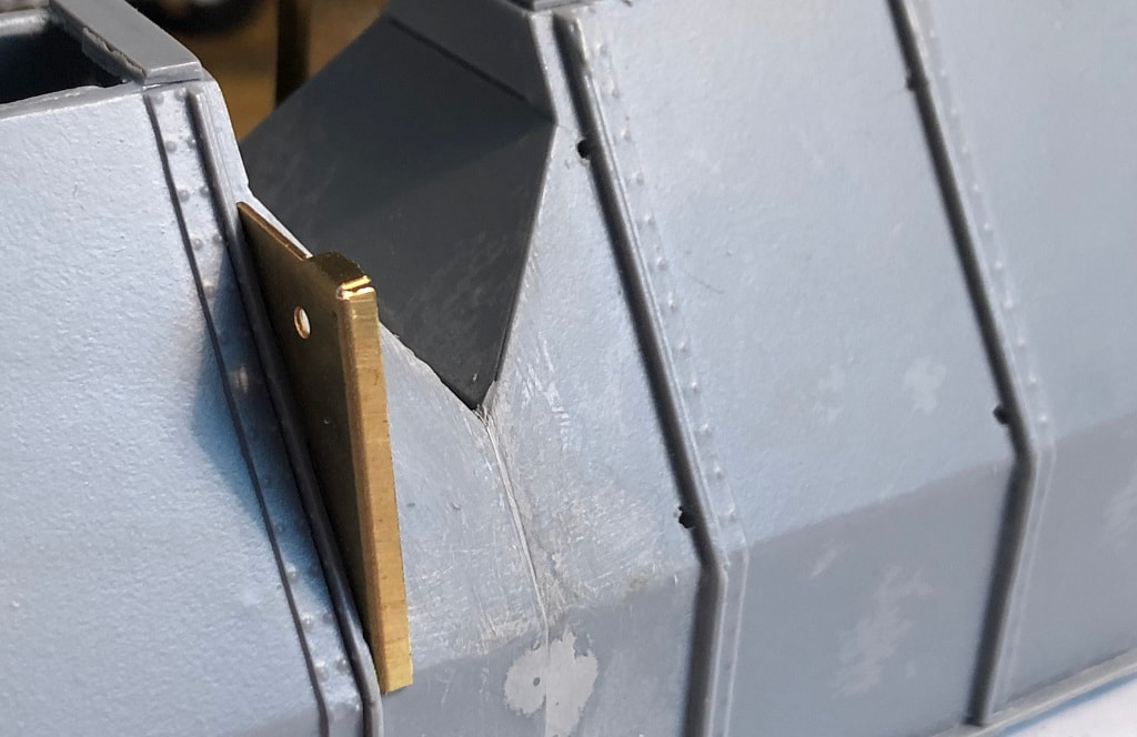
Once set the first parts to attach to the hopper body are the strake brackets, cut these from the etch and once any burrs are removed bend the edges along the etch lines. Note these are handed and there are two different brackets for each side (one side has holes in and the other is plain). The cross-tunnel cover can also be riveted and fitted at this point, I forgot and had to squeeze it in later in the build.
|
|
|
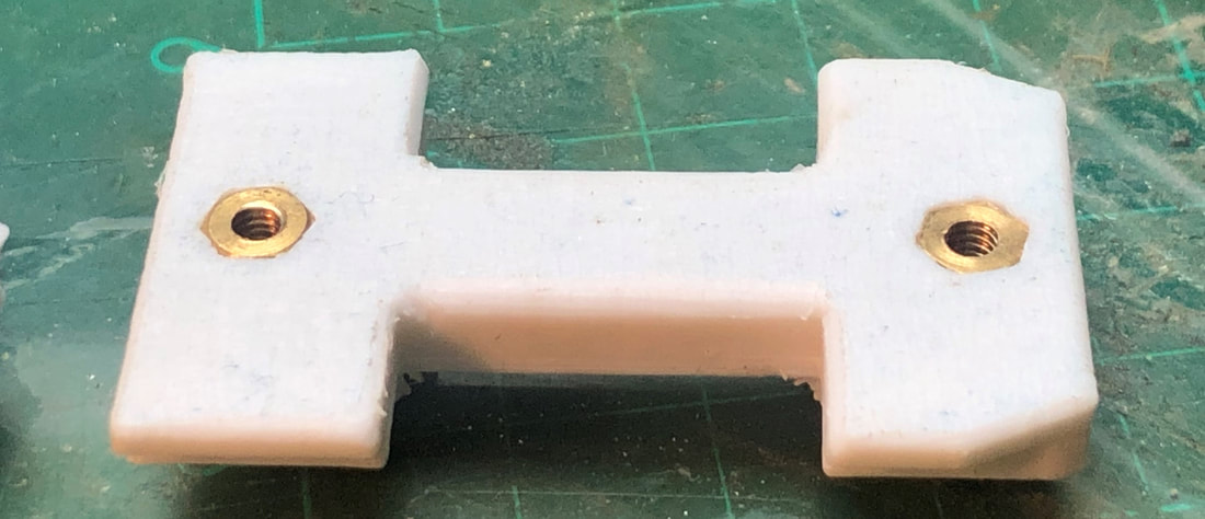
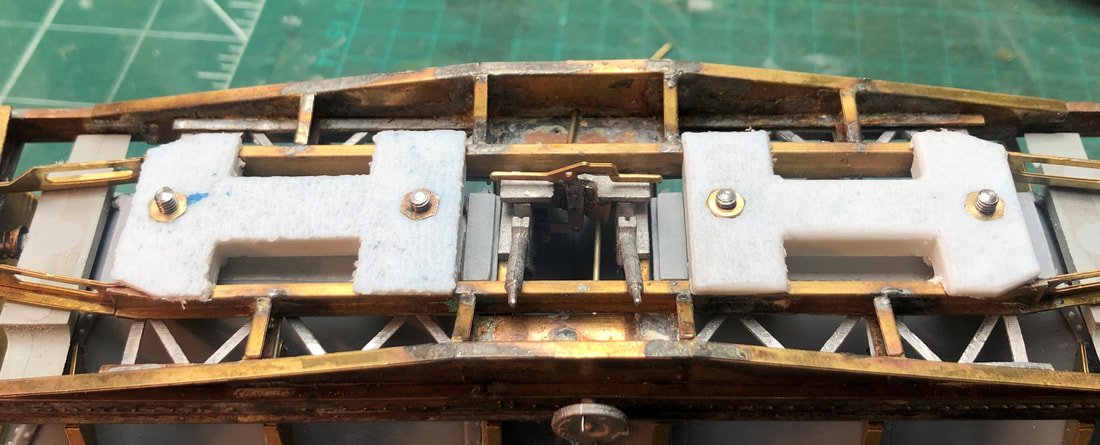
There are two aluminium clamp bases and two plastic clamp bases joined together with a 6BA screw and nut. The plastic bases need filing so they are a snug fit between the chassis rails, with the aluminium bases dropped into the body of the hopper, I secured these with a dab of super glue.
Once set the bottom door covers can be added, again I secured these with super glue but the instructions suggest using blue tac so you can remove the body should you desire. Finally adding the tank floor bridges. |
|
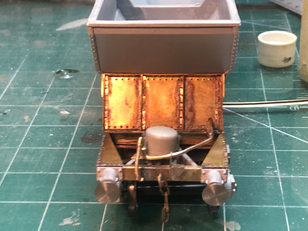
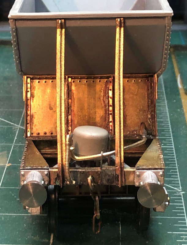
Now I didn’t follow the instructions fully here again and ended up with an issue, but we’ll work through my method here! I ran the 1.5mm wire through the holes in the strake bracket s fitting a 6mm piece of tube to each end, then adding the vacuum pipes and brackets onto the end of the buffer beam assuming everything would fit together and it would be easier to add these now before adding the tank end support beams.
|
|
|
|
How wrong was I, the support beams didn’t now fit properly, back to the drawing board, or at least back with the soldering iron to undo a few of the bits I had soldered together! After adjusting the pipework on both ends the tank end supports would now sit in place without the pipework fouling them. These were tinned at the bottom of the support before tacking to the top of the tank with superglue then warming the bottom part onto the buffer beam with the soldering iron.
|
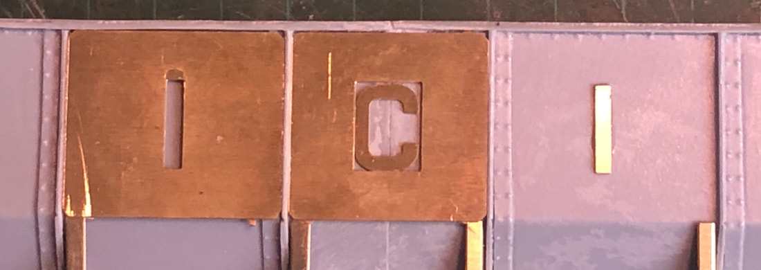
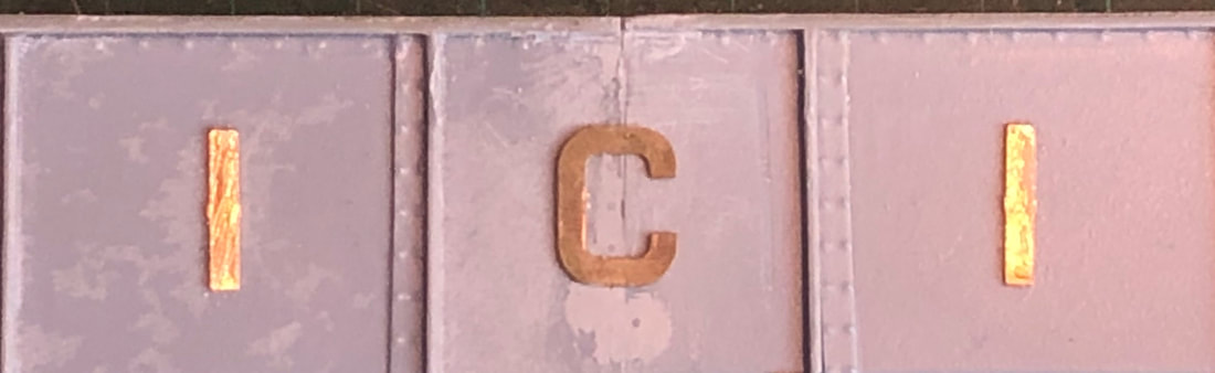
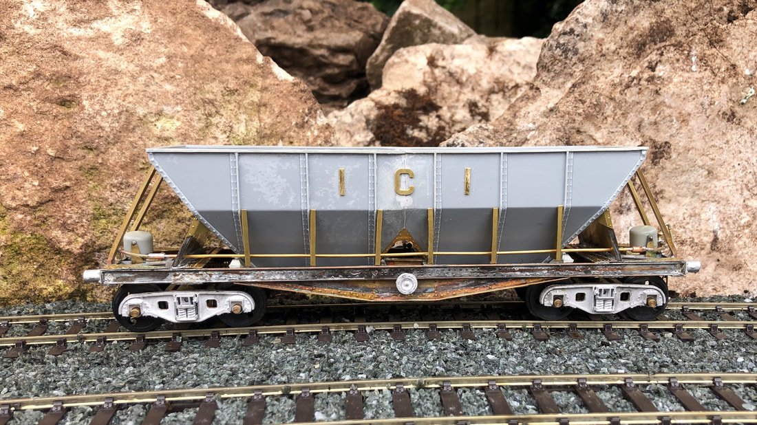
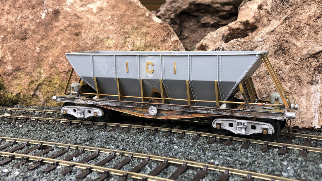
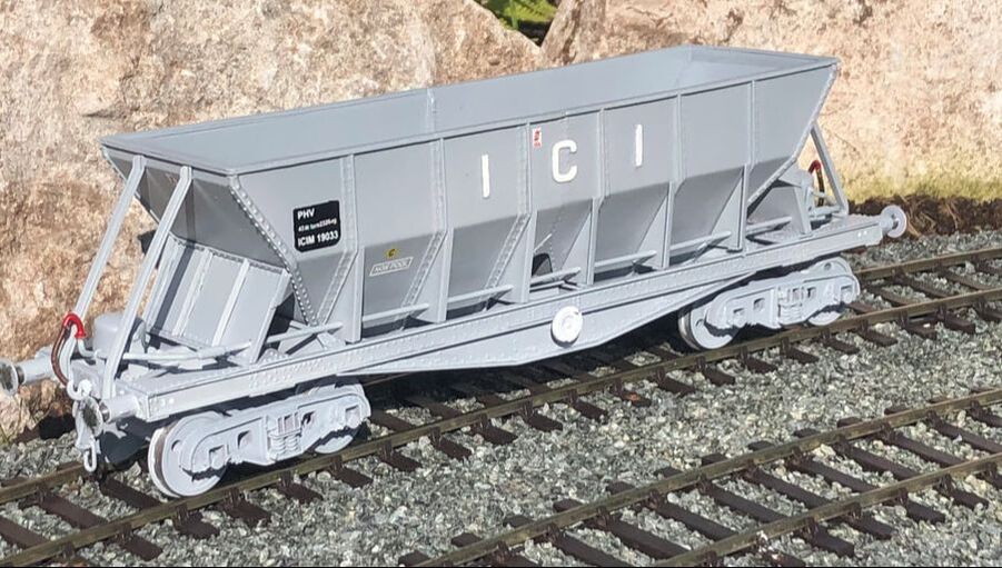
Final job on the body is fitting the ‘ICI’ lettering, there are etched spacers to assist in positioning theses which are a great help to getting them square.
|
|
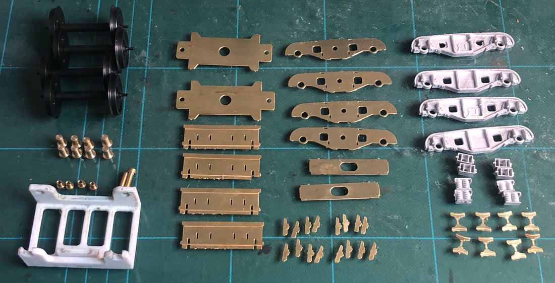
Bogies
The bogies are made up as is common with many bogie wagon kits of a brass subframe with white metal overlays. Where this kit differs is that it uses ‘rocker pins’ to give the bogies better movement and the novel addition of a 3D printed frame to help with getting the assemble square but more on that shortly.
|
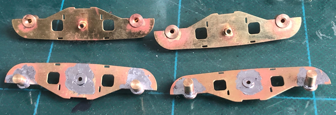
Brass bearing’s and the ‘Rocker Pins’ are first slotted into the subframe sides and all three soldered in from the outside. Note that the ‘Rocker Pin’ is fitted the opposite way to the bearings.
|
|
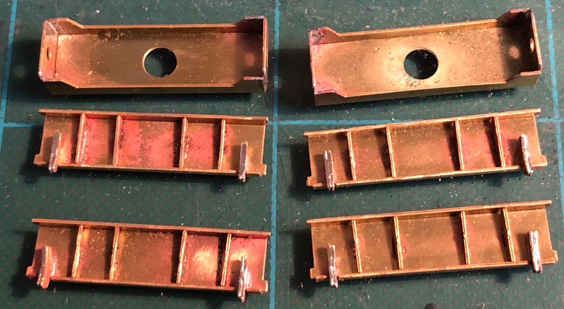
The main bolster is one piece folded up into a box with a little solder run along the joints from the inside to give it some strength. With a round file open out the hole where the ‘Rocker Pin’ fits until it moves freely. The main bogie bracing is folded up into a ‘U’ shape with four braces & brake shoes soldered into tabs in the ‘U’ section. The brake shoes are two parts soldered together, as per the instructions when cutting these parts out DO NOT CUT THE FRET BETWEEN THE PAIRS OF SHOES, this helps when soldering them together. I bent them into pairs and soldered along the front face of the shoes, this can then be filed back with a half round file. Once the bracing and brake shoes are soldered into the ‘U’ channel I trimmed the tabs of the brake shoes and filed the tabs back. Make sure when you solder these parts in the tabs are pushed firmly home otherwise you will end up with problems with the wheels running freely when finally putting the bogies together.
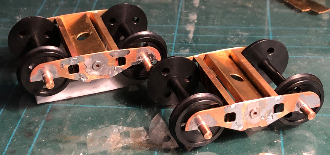
This is where the 3D printed frame comes into its own! Place one of the subframe side frames into the closed side of the frame, then add the bolster and frames with the brake shoes fitted into this side finally adding two wheel-sets. Lastly you need to fit the opposite subframe side, I found this easiest by putting the frame on its side. Once you have everything fitted up, you can carefully remove the whole bogie from the frame if you want to by holding it with a finger and thumb pinching the two ‘Rockers Pins’ together. This helped me make sure that both wheel-sets spun freely before soldering all the tabs in place. Place the bogie back in the frame and solder the four tabs on each side frame and you should now have a nice freely rolling bogie!
|
Drop a 6BA bolt through one of the washers and though the fixing point on the bogie and you can solder the bottom stretcher plate in place. The instructions recommend temporarily holding the bolt in place with blu tack or the like, but I popped another washer and a nut over the other end to hold it in place, these can then be removed when you come to fix the bogies to the chassis.
|
|
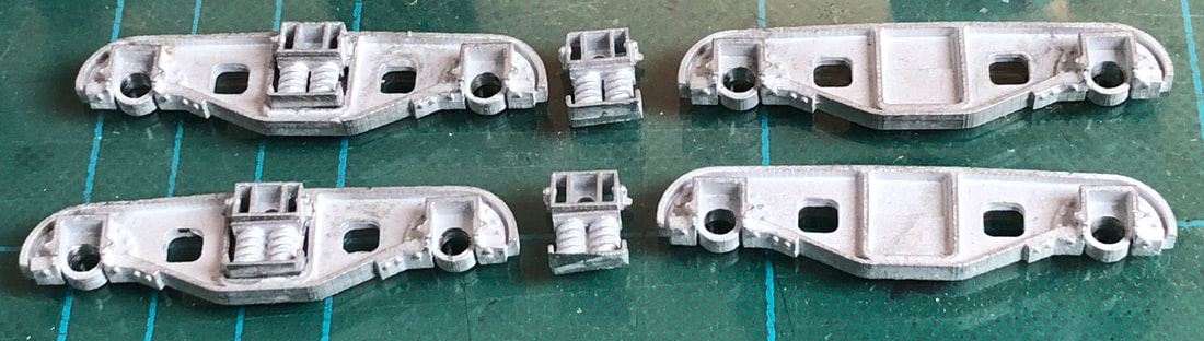
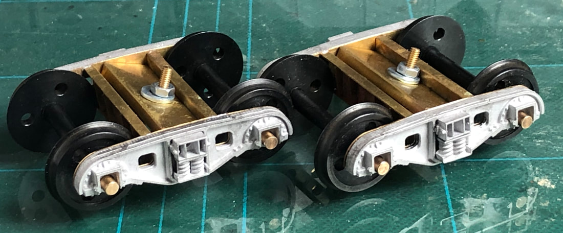
Now for the white metal overlay. I found a little flash on a couple of my side frames but this is easily removed with a suitable file. The frames should be a snug fit over the wheel barring’s but may well need opening out with a round file. Mine did and this was done on a trial & error basis filing and checking repeatedly until I was happy with the fit. Once you are happy with the fit, the springs and spacers can be fitted with a little super glue. When dry these frames were then super glued to the brass frames.
|
|
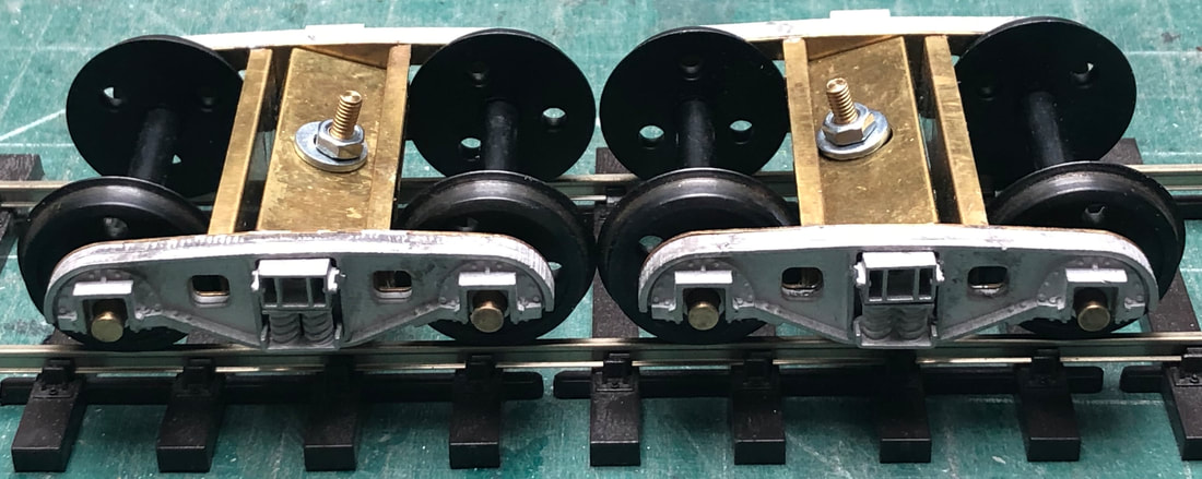
The bogies were then trial fitted to the rest of the wagon.
|
|
|
Paint, Transfers & Final Finishing
|
After a good wash and being left to dry overnight I started off with a couple of coats of grey primer. Now earlier on you may recall me mentioning that I decided not to worry too much about the rivets on the join between the two halves of the hopper body as I wanted to ensure I got a good join between them and I am not as delicate with things sometimes as I maybe should be, therefore at this point I replaced the rivets with some of the Archers transfers from DCC Supplies. I didn’t worry too much about silvering as they will be covered in paint.
|
|
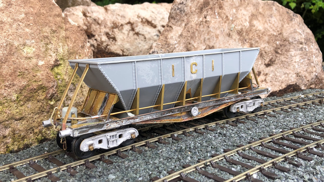
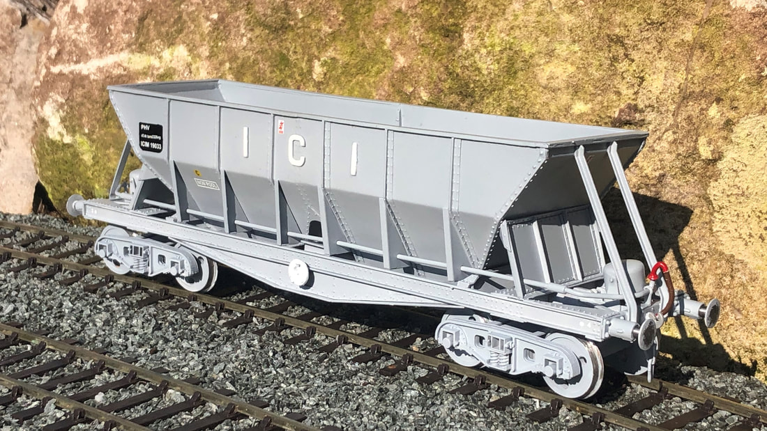
Once the rivet transfers had dried fully, I topped these with a couple more coats of primer but this time in white to give the grey final coat a nice light base. As I am still not prolific with an airbrush I was unsure as to what colour to use for the top coat. I had found a rather nice picture on Flickr.com of a newly outshopped hopper at Northwich in 1987 but unsure of the correct shade. After looking at various shades of grey in spray can form, I settled on a can of Revell No. 76 USAF grey which I think is quite a good match.
The white ‘ICI’ lettering and hand brakes were subsequently picked out in white along with various handles and vac brake fittings in red. A small square has also been panted black for the wagon numbers. Once all the paint was completely dry, I then spayed the whole wagon with a couple of coats of gloss varnish in preparation for transfers.
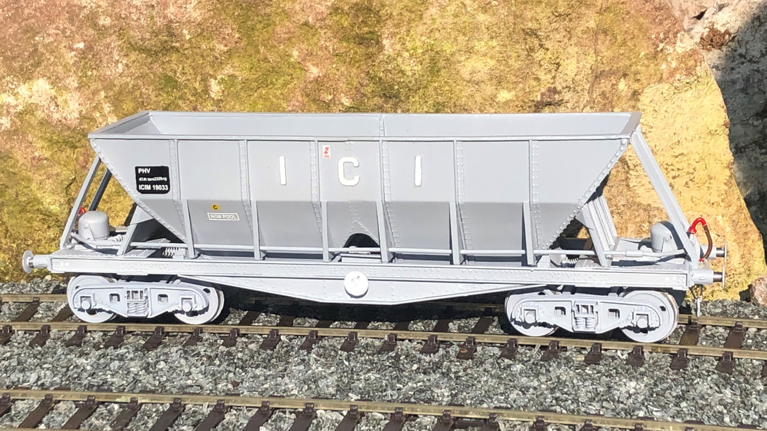
The kit comes with an extensive selection of Pre-TOPs and TOPS numbers, the only thing I have added is the warning flashes most modern modellers will likely have a stock of. The kit also comes with wagon plates but I have left these off as in later years a number of them were missing.
The white ‘ICI’ lettering and hand brakes were subsequently picked out in white along with various handles and vac brake fittings in red. A small square has also been panted black for the wagon numbers. Once all the paint was completely dry, I then spayed the whole wagon with a couple of coats of gloss varnish in preparation for transfers.
The kit comes with an extensive selection of Pre-TOPs and TOPS numbers, the only thing I have added is the warning flashes most modern modellers will likely have a stock of. The kit also comes with wagon plates but I have left these off as in later years a number of them were missing.
|
|
In Conclusion
This is a great kit of an iconic prototype which has been well thought out with some innovative ideas (the bogie frame and various ‘tools’ to help positioning of parts). At times I found it a little frustrating but any issues are easily overcome with a little thought and a clear head! If you are confident with building brass kits it is well worth the effort, if not then I would recommend building a couple of wagons which may be a little simpler to start with. It has certainly stretched me and I have learnt a number of things along the way. I will now be going back to some of my older brass kits which have never been finished with a new found confidence and a better idea as to how to approach them.
Signature Kits ICI hoppers can be ordered either in kit form or RTR by emailing either John Firminger or Ian Gould at [email protected] or [email protected] .
Signature Kits ICI hoppers can be ordered either in kit form or RTR by emailing either John Firminger or Ian Gould at [email protected] or [email protected] .